We visited NXP's Tokyo office yesterday and met up with Okano-san and Azechi-san. We had met them previously at Maker Faire Tokyo, and mentioned that we were looking into developing a kit using NXP's ARM Cortex microcontrollers.
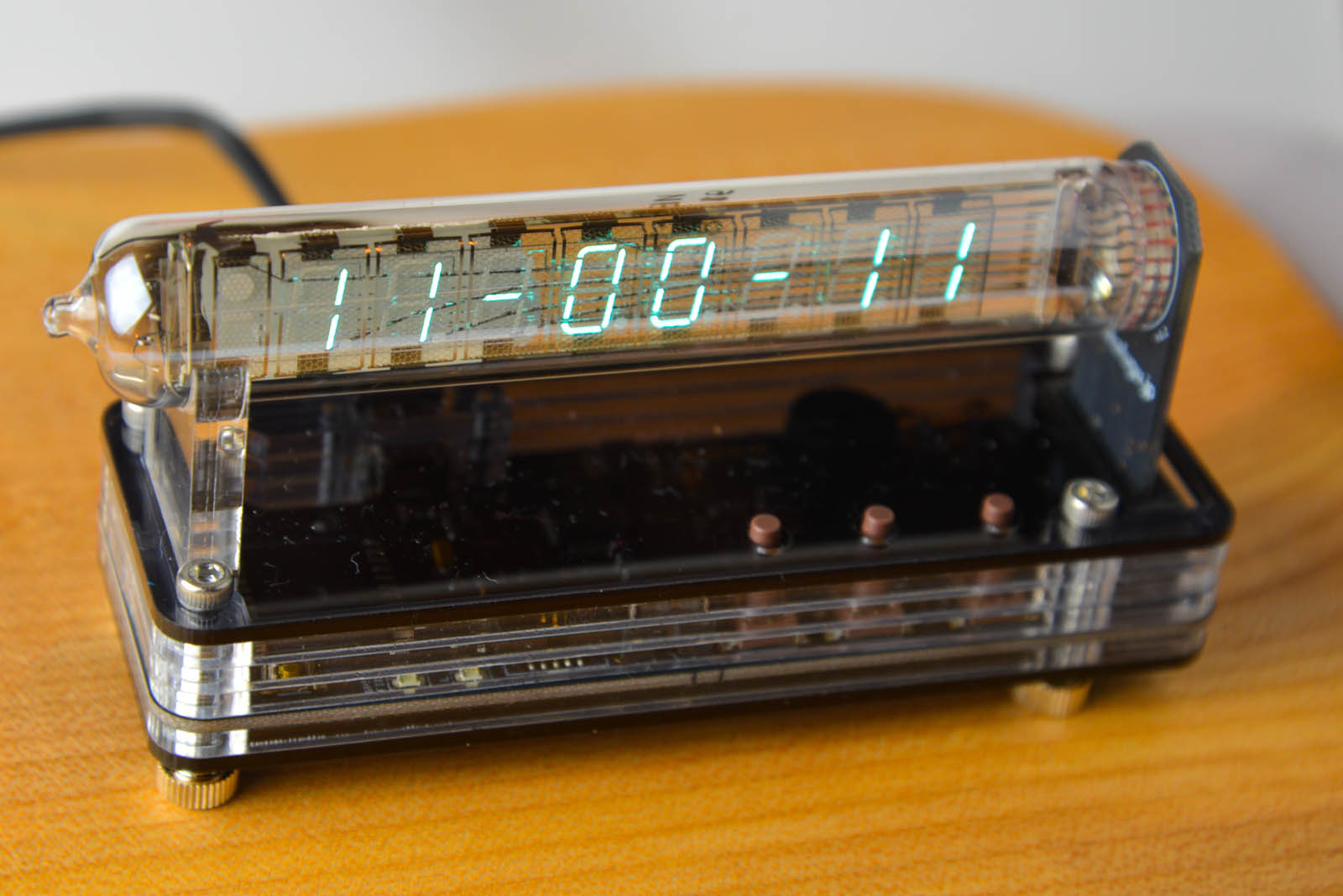
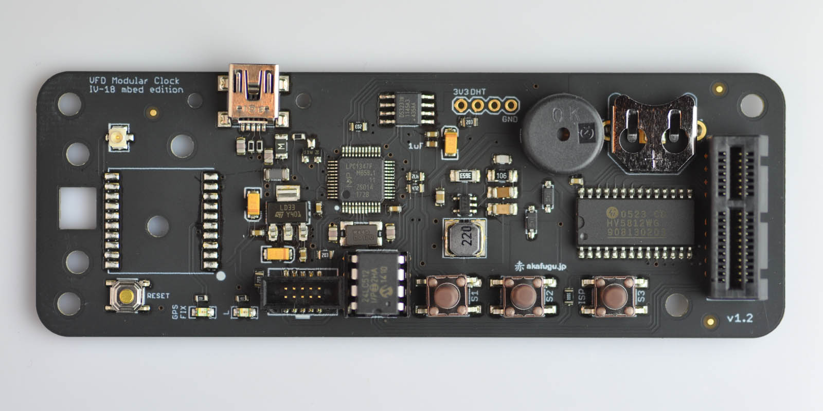
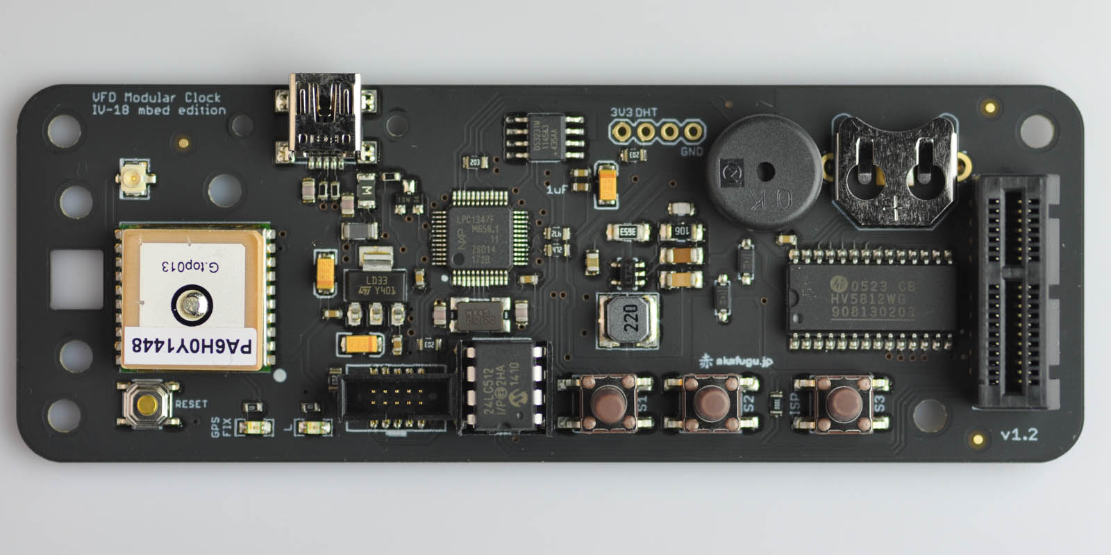
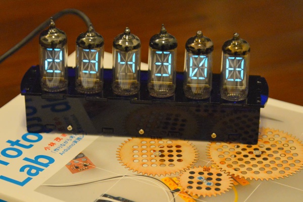
We went to their office to show them our new VFD clock board: VFD Modular Clock IV-18 SMT mbed Edition. This clock is a new experiment for us, a new non-solder kit where all the parts are pre-assembled SMT parts, but the enclosure comes as a kit, so that some assembly is still required.
As an effort to widen our horizons, we've been playing around with mbed for the last year or so. The mbed project has been growing a lot lately, and is very popular here in Japan with many domestic contributors. NXP was one of the first participants in the mbed project, and the first few mbed boards were all based on NXP microcontrollers. Since then, the platform has expanded and now includes ARM Cortex chips from several manufacturers. Things like UART access, I2C/SPI, PWM and interrupts work effortlessly across platforms. Other things like DMA and low power modes still require processor-specific code, but we expect this to improve in the future.
The NXP chips were the most viable for us to use for our first ARM Cortex-M kit for several reasons:
On-board USB 2.0 with embedded USB bootloader. When you plug the board in and put it in bootloader mode, it simply shows up as a mass storage device where the firmware can be copied into with no other programmer required. This is a huge plus for a kit, since it means that all our customers need in order to change the firmware is a computer with USB.
Easy access to a debugger. The mbed development boards all have an onboard mbed interface chip with debugger (CMSIS-DAP). For standalone boards, such as our kit, it is easy to get hold of a standalone debugger in Akihabara. The LPC-Link 2 debugger is available either standalone, or embedded in the new line of LPCXpresso 2 boards (to debug either the internal processor, or an external one). Both are easy to get in our favorite Akihabara shop, Akizuki Denshi.
We started off the project with the LPC11U24 Cortex-M0 32k microcontroller. The emphasis of the firmware was to make something simple to modify, not necessarily something heavily optimized. Just as you'd expect from a framework that aims to abstract away differences between different microcontrollers, you pay for this in a larger binary size than you would get working directly on metal. As we kept adding features to the clock, the code size started creeping up to 32k quickly, so in order to give some flexibility for future customer mods, we decided to bump the microcontroller to a 64k one. The LPC1347 Cortex-M3 64k microcontroller is pin compatible with the LPC11U32, and also supported by mbed.
We also managed to score some swag at the NXP office:
We're aiming to release the new clock within the next week or two. It will be on sale both on our store and on the Amazon Japan store.
Feature highlights include:
- Open source mbed firmware (you can find it here)
- GPS module
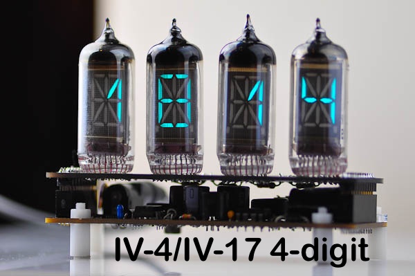
- Four Letter Word mode
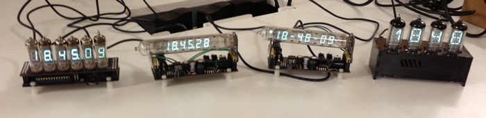
- IV-18 display tube
- Powered from USB (either a computer or a 5V 0.5A or higher USB wall adapter like the type that usually comes with cellphones)
- Stylish Acrylic enclosure (produced by Emerge+)