The cMoy Headphone Amplifier is easy to assemble, and requires only basic soldering skills.
To make the amplifier, you will first solder the components to the PCB, test it with your audio player, then assemble the case and mount your amplifier inside.
The amplifier kit is for sale in two variants:
- Standard case: Aluminum case with arcylic front and back panels.
- Deluxe case: Aluminum case with aluminum front and back panels.
The two case variants have virtually the same assembly steps. When there are differences, they are noted in the text.
Requirements
To assemble this kit, you will need:
- A soldering iron
- Solder
- A wire cutter (a diagonal type that allows you to cut the wires as close to the soldering points as possible is best)
- Helping hands or clips to hold the PCB in place when soldering (a vise will also work)
- Pinchers
- Screwdriver (*)
- Cheap set of headphones for testing
- 9V battery
- Audio player (such as a smartphone)
Optional:
- Desoldering wick
- Solder sucker
- Protective glasses
See the equipment page for more details.
Screwdriver bits
For case assembly, you will require the following bits:
- 2.5 allan bit -or- T-10 torx bit (deluxe case requires torx bit)
- 1.5 allan bit -or- T-6 torx bit
- Philips bit
Preparations
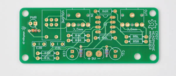
First, familiarize yourself with the PCB.


Step 1 - First Resistor
The kit contains 11 resistors. It is important that they are placed properly, otherwise the amplifier will not function correctly.
The following resistors are included:
- 1x 10kΩ (Brown, Black, Orange, Gold) 1/6W 5% resistor (R1)
- 2x 4.7kΩ (yellow, violet, black, brown, brown) 1/6W 1% resistor (R2)
- 2x 100kΩ (brown, black, black, orange, brown) 1/4W 1% resistor (R3)
- 2x 47Ω (yellow, violet, black, gold, brown) 1/4W 1% resistor (R6)
Gain Resistors
- 2x 10kΩ (brown, black, black, red, brown) 1/4W 1% resistor (R5)
- 2x 2kΩ (brown, black, black, brown, brown) 1/4W 1% resistor (R4)
- 2x 4.7kΩ (yellow, violet, black, brown, brown) 1/4W 1% resistor (R2)
We will use either the 2k or the 4.7k resistors to set gain, not both. Unless you have large and hard to drive headphones, we recommend using 4.7k.
You can use the color codes on the resistors to read the values, but this is often difficult to do properly, especially in dim light. We recommend double-checking all resistor values with your multimeter set to RESISTANCE mode before soldering.
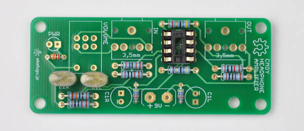
Let us start with the small 10000Ω resistor. This resistor has a brown body (all the other resistors have a blue body).
Bend the legs 90 degrees to insert into the footprint marked R1 on the PCB. Resistors are not polarized, so orientation doesn't matter. Insert it and pull the legs so that the body of the resistor lies flat against the board. Bend the legs outward slightly so that the resistor stays in place when you turn the board over.
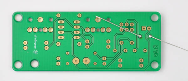
Solder both legs and then use a wire clipper to trim off the excess part of the legs.

Done:

Step 2 - Remaining Resistors
Let us solder the remaining resistors. These resistors are all 1% tolerance resistors with a blue body. They come in pairs. For example, the 4700Ω resistors go to R2L and R2R (for left and right channel respectively). The same arrangement is used for all the remaining resistors.
We'll start with the two 4700Ω resistors. These are smaller than the remaining ones, and go to R2.
The remaining resistors are all the same size and body color. You can solder them one at a time, in pairs or all at the same time, depending on your soldering skill level.
R3 100000Ω:
R4 2000Ω - or 4700Ω:

The resistor chosen for R4, together with the 10k resistor in R5 will set the gain of the amplifier.
The gain is calculated as follows:
Gain = R5 / R4 + 1
- Using 2k: gain 6
- Using 4.7k: gain 3.1
For use with small and/or sensitive earphones, we recommend using the 4.7k resistor. Most modern headphones are sensitive and will work well with the 4.7k resistor.
The 2k resistor will also work with sensitive earphones, but be careful when setting the volume: Setting it too high may damage both your headphones and your hearing!
If you find that using the 4.7k resistor gives too little volume on your earphones, you can always change them for the 2k resistor later.
If you want to experiment with different gain settings, make sure to use high-quality 1 % resistors, otherwise there may be an audible inbalance between the left and right channel.
R5 10000Ω: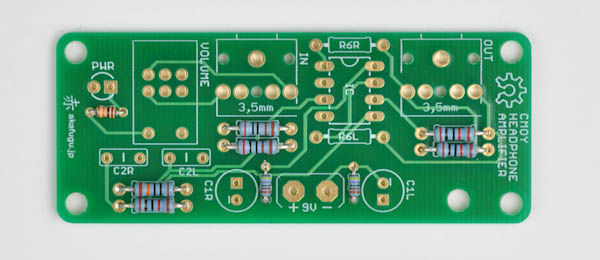
R6 47Ω:
Step 3 - IC socket
Place the 8-pin IC socket.
Make sure it is oriented so that the half-circle indentation matches the half-circle drawing on the PCB.
The component may fall out when you turn the board over to solder. You may use a small piece of masking tape or similar to hold it in place.Solder only one leg first, then check that the orientation of the component is correct. If not, re-apply heat and adjust as neccesary. Once you are happy with the orientation, solder the remaining legs.
Step 4 - Film Capacitors
There are two 0.1uF film capacitors included. Film capacitors are not polarized, so orientation doesn't matter. They are soldered in the same way as the resistors.
Step 5 - Electrolytic Capacitors
There are two 220µF electrolytic capacitors included.
Electrolytic Capacitors are polarized and must be inserted the correct way. The long leg goes in the square hole. The short leg goes in the round hole (marked with a minus sign)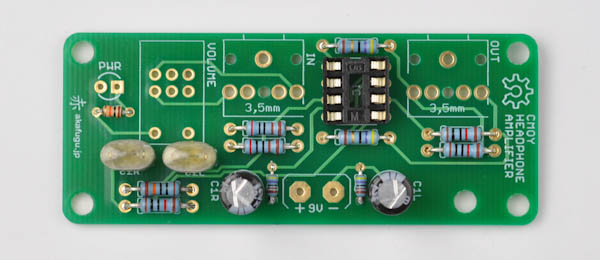
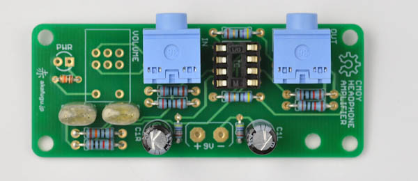
Step 6 - Audio Jack Connectors
There are two jack connectors, which go to the connectors marked IN and OUT. The connector will only fit one way.
Note that the color may not match the one shown in the picture.
Step 7 - Potentiometer
Next, solder the potentiometer to the footprint marked VOLUME. It will fit only one way around.
The potentiometer comes with a built-in on/off switch.

Step 8 - Battery connector
Find the 9V battery connector, and trim off about half of each of the two wires. Then strip the insulation of about 1/2 cm on each end and add some tin to each end.
Now solder the two wires: The black wire goes to minus (-), the red wire goes to plus (+).
Be careful when inserting and removing the 9V battery, as the connector may break if you pull to hard.
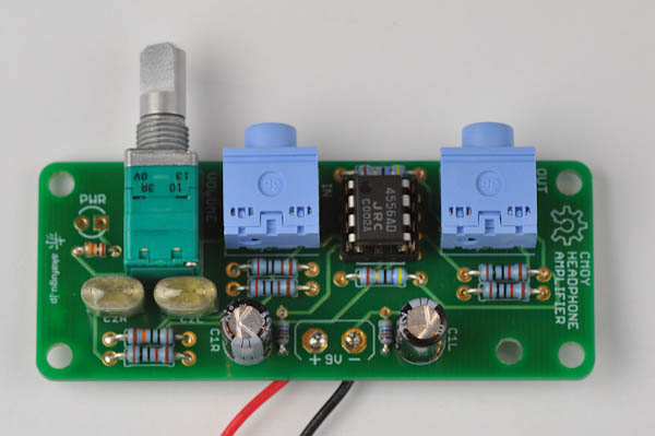
Finally: Place the 8-legged OPAMP chip. It must be placed so that the dot or half-circle indentation on the chip matches up with the half-circle indentation in the chip socket.
Step 9 - LED -or- Enclosure assembly
For the included enclosure, we will solder the LED as part of the case assembly process.
IF YOU PLAN TO USE YOUR OWN ENCLOSURE:
There is now only one component left over: The power LED. If you plan to use the amplifier with your own custom enclosure, you may solder and place the LED as you wish: It is polarized, so make sure to insert the long leg into the square hole.
ENCLOSURE ASSEMBLY
There are two variants of the case available: Standard and Deluxe. They are both based on the same Takachi MX2-8-7 basic case. The standard case comes with custom acrylic front and back panels. The standard case comes with custom aluminum front and back panels.
The assembly is mostly the same, and any differences will be noted in the text.
Step 1
Standard Case:
Takachi MX2-8-7 case with custom parts:

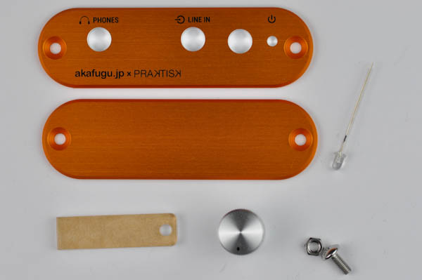
Deluxe Case:
Takachi MX2-8-7 case with custom parts:
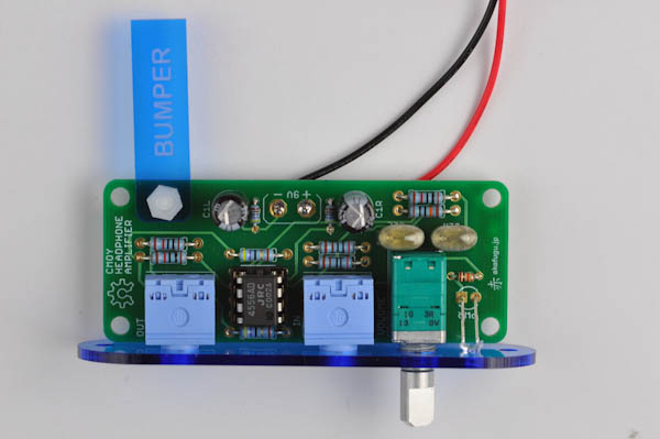
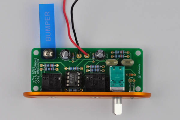
Step 2: Bumper
Attach the enclosed BUMPER to the PCB board using the enclosed screw and nut. (note: appearance of screw and nut may be different in shipping version).

Step 3: Mounting the LED
Insert the LED into the front panel as shown: The long leg of the LED should point to the left side.
For the STANDARD CASE, use the flat top blue LED that is included in the amplifier component bag.

For the DELUXE CASE, we will instead use the round top orange LED that is enclosed together with the case.
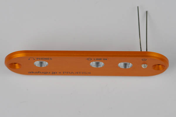
Bend the legs 90 degrees down. Insert the legs of the LED into the PCB (long leg goes the the square hole) and push in the front panel to the front of the PCB so that the holes line up with the connectors.

Step 4: Aluminum Enclosure
Next, open up the included Takachi case.
STANDARD CASE:
If your case came with plastic end panels, discard them. Also discard the eight screws that are enclosed together with the aluminum panels.
We will use the four black allan M3 screws included separately to fasten the front and back panels. You will need a 2.5 allan bit for this.
The screw holes are not tapped, so be very careful when fastening the allan screws: Be sure that the angle is good and go slowly.
Remove the protective film from the acrylic before assembly.
DELUXE CASE:
The Deluxe case comes with the following screws:
- 4x M3-14 silver Philips screws
- 4x M3-14 black Philips screws
- 4x M3-14 black Torx screws (requires T10 torx bit)
The screw holes are not tapped, so be very careful when fastening the screws: Be sure that the angle is good and go slowly.
The case only requires four screws: We recommend using the torx screws. You can also use the silver Philips screws for tapping and then remove them and switch to the torx screws.
If your case came with plastic end panels, discard them.
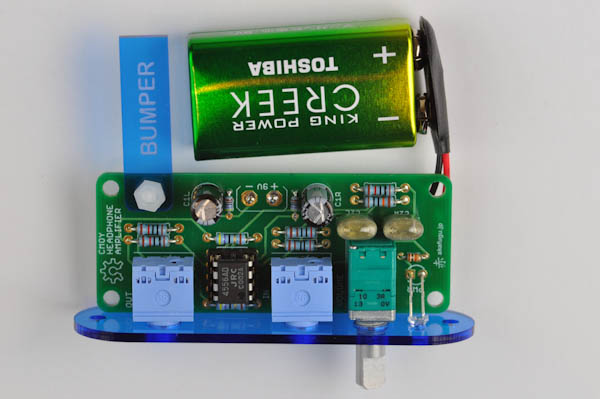
Step 5 - Insert the battery
Let us insert the battery into the battery clip.
Step 6 - Test run
The next step is a test run of the amplifier. You will need the following for this:
- mini-jack to mini-jack connector
- headphones (we recommend using a low-quality cheap set to test, so as not to risk damaging expensive ones)
- an audio source, such as an ipod.

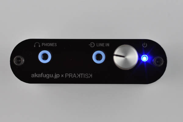
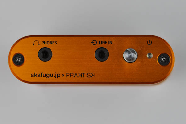
Connect one end of the mini-jack connector to your audio source, the other to the connector marked LINE IN on the amplifier. Then connect the headphones to the connector marked PHONES.

Now, carefully twist the volume control: You should see the LED illuminate
Next, start music playing on your audio source. Insert the headphones into your ears, and try adjusting the volume very gently. For best results, don't set the volume on your audio source too high: About 50 % usually works well.
Strange behavior, distortion, extremely high volume or extremely low volume in this step usually indicates a soldering error or misplaced resistors.
Step 7 - Inserting the PCB
Once you've verified that your amplifier works, you can disconnect everything and insert it into the enclosure.
Standard case: The allan screws will require a 2.5 allan bit or T-10 torx bit to fasten.
Deluxe case: The torx screws will require a T-10 torx bit to fasten.
Insert the PCB with front panel, and fasten two of the screws:

Adjust the battery so that it fits snugly in the back. Then insert the back panel and fasten the two remaining screws.

The battery may rattle a bit. To fix this, you may add some adhesive foam padding inside the top and bottom of the aluminum casing (not included).
Step 8 - Volume knob
The knob of the left hand side is bundled with the deluxe case. The one on the right hand side is bundled with the standard case.
Note: The appearance of the volume knob may vary slightly from what is pictured here.

For the type pictured on the left:
Insert the volume knob, and fasten it to the shaft by using a 1.5 allan bit or T-6 torx bit (there are one or two screw holes on the volume knob that are used for fastening)
For the type pictured on the right:
The knob will only fit one way. Gently push it onto the shaft. No screw is used.


Congratulations! Your cmoy amplifier is now fully assembled. Now go enjoy your music!