At first glance the 4x4x4 RGB Cube (which we often just call the "Cube4") may seem very complicated to assemble because there are so many parts. However, it's not as difficult as it may look, and at the end you'll be proud to show it off and tell people that you built it! Just take it slowly and carefully, make sure you understand the instructions before you begin, and be careful to follow each of the steps without skipping ahead.
In addition to the text and photo instructions below, we've also created an instructional video that demonstrates construction of the Cube4 from start to finish:
1) Check Parts List
The Cube4 kit contains the following items:
- 1 x "Cube USB" controller board
- 1 x micro USB cable
- 8 x "stick" PCBs labelled Y0, Y1, Y2, Y3, Z0, Z1, Z2, & Z3
- 4 x "plane" PCBs (identical)
- 64 x 8mm RGB LEDs
- 4 x black plastic stand-offs with threads
- 4 x black plastic nuts

Lay the parts out on a bench and check them against the parts list. It's a good idea to tip the LEDs into a small container to prevent any getting lost: don't just let them roll around on the table. A take-away food container with a lid is perfect.
2) Gather Required Tools
Assembling the Cube4 requires soldering, and you'll need to connect it to a computer in order to program it. Make sure you have the following items:
- Soldering iron
- Fine solder
- Side cutters
- A square-edged book or builder's set square
- Optional: masking tape, rubber bands, and/or Blu-Tac
The rest of these instructions assume that you know how to solder. If you're unsure or need some pointers on good soldering technique, please see the references on Freetronics's How To Solder page page.
3) Fit RGB LEDs to Plane PCBS
Each of the four plane PCBs needs 16 RGB LEDs fitted to it. There are two things to be very careful of with this step, and if you get either of them wrong you'll have a very hard time trying to fix it so make sure you do it right the first time.
Firstly, make sure you have the plane PCBs the right way up. Look closely on the central connectors, and you'll see the URL "www.freetronics.com" printed very small in the middle. That indicates the top of the plane PCB, so put them down on the bench in front of you with the URL up. The bottom of the plane PCBs are blank with no text on them.
Secondly, check every LED very carefully as you fit it to make sure you do it the right way around. The LEDs have four legs, with one leg longer than the others. It's critical that the longest leg goes into the correct hole in the plane PCB for your Cube4 to work properly. You'll kick yourself if you get to the end, turn it on, and discover that one or more of the LEDs is fitted backwards.
Look closely at the plane PCB and you'll see that the second hole in each LED location has a small white bar above it, and the gold pad is square instead of round like the other holes. The LED must be inserted so that the longest leg goes into that hole, as shown here:

You will need to gently spread out the legs of each LED to insert it into the plane PCB, then wiggle it down until it sits firmly about 5mm above the PCB. Here's a close-up to help you identify the correct orientation and position:
Depending on how confident you feel, you can either fit and solder the LEDs one at a time or fit them all and then solder them in one go. Here's a view of a plane PCB upside down with all the LEDs inserted and soldered, ready for the leads to be cut off:

Now is the time to make one last check that you put in all the LEDs the right way around. Hold up the plane PCB and look along the rows of LED leads, making sure that the longest leads are all in a row and none are inserted the wrong way around.
If you're happy with the assembly so far, use a pair of side-cutters to trim off each lead just above the solder joint. It's a good idea to hold the leads as you cut them so they don't fly off and stick in the carpet or your eye.
Once you're done, you'll have a plane PCB complete with 16 RGB LEDs fitted to it, like this:

One down, three to go. Repeat this whole step for each of the four plane PCBs.
4) Fit Controller Board Standoffs
The Cube4 controller board is designed to be used "upside down" compared to a typical PCB. All the parts are mounted on the bottom so they are hidden away once the Cube4 has been assembled, so they need special protection to stop them being bashed around when you put the Cube4 down.
The four black plastic standoffs screw through the four corners of the controller board from underneath (the component side, remember) with nuts on top to hold them in place. Put them in place and screw them up finger-tight: don't put too much pressure on them using pliers because you can strip the thread. See the next step for an example of how the controller board sits on the standoffs.
5) Prepare Stick PCBs
The eight "stick" PCBs are supplied attached to carrier strips, so you need to separate them out. There is a small groove in the PCB material at each end of every stick, so by grasping the carrier strips in your fingers or a pair of pliers you should be able to wiggle it back and forth until the sticks break free. Be careful not to break the sticks themselves!
If you look closely at the sticks you will see they have unique designators on them, corresponding to designators on the controller board. Sit the controller board in front of you on a flat bench so that the URL and Freetronics logo is facing you, as shown below, and lay out the sticks beside it so that the stick designators match the positions on the controller board.

It's very important that you match up the stick positions to the controller board, because if you get them in the wrong spot your Cube4 won't work.
6) Fit Reference Sticks
Assembling the 3D structure of the Cube4 is probably the most tricky part of the whole process. There are many ways you can do it, but having assembled many Cube4s ourselves we think the method we'll show you here is the simplest.
Use your soldering iron to "tin" just one of the pads on the controller board for the Y3 stick, which should be at the back left if you have the Cube4 sitting as shown in the photos. "Tinning" means flowing a little bit of solder onto the surface with your soldering iron, without attaching anything else to it.
Next, tin the corresponding pad on stick Y3 so that it has a light coating of solder on it. Note that the sticks have to be fitted so that the little notches on one side are towards the middle of the controller board, so check the orientation before you tin the pad.
Now hold the stick in place in the controller board, trying to keep it as straight as possible, and use your soldering iron to "re-flow" the solder between the pad on the controller board and the pad on the stick. This will hold the stick in place temporarily. Don't solder the other joints yet, because that will make the joint very strong and you won't be able to adjust the alignment of the stick.
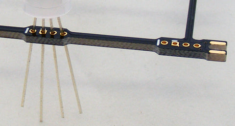
Now it's time for fine adjustment. If you have a builder's set square, sit it on the workbench next to the controller board and use it to check whether the stick is properly vertical both left/right and front/back, like this:

You can also see in that picture the correct orientation of the stick, with the notches towards the middle.
If you don't have a set-square, don't worry, you can use a square-edged book to achieve the same result:

Use your soldering iron to re-flow the solder on the pad several times if necessary, adjusting the stick until you're confident that it's as perfectly vertical as you can manage. When you're satisfied that it's right, solder the other three joints between the controller board and the stick, using just enough solder to generously bridge the gap between the horizontal and vertical pads. Make sure the solder has adhered properly to the pads and hasn't just pooled on one side of the joint or the other.
The next stick to fit is Y0, on the front left of the controller board. Use the same technique, but this time you have the benefit of the first stick in place as a reference. In addition to checking that it's square, you can measure between the tops and bottoms of the sticks to make sure they're the same distance apart at the top as they are at the bottom. In the following photo it looks like they're out of alignment, but that's just because of the camera angle. They're actually perfectly aligned, and yours should be too:

Repeat the process for the other left sticks, Y1 and Y2. You should now have the left side structure of your Cube4 all in place:

Make sure all four solder joints are complete on every stick.
7) Position Plane PCBs
This next step is tricky to explain, but should make sense when you try to do it yourself.
Pick up one of the plane PCBs that you prepared earlier, and slot it sideways into the bottom position on the four vertical sticks. Wiggle it into position until the place PCB is neatly settled in the notches in the sticks to set it in the correct vertical position.
Next, without letting go of the plane PCB, use your other hand to pick up one of the middle sticks for the right side (either Z1 or Z2) and pop it into position. By aligning the plane PCB with the notch in the right hand stick you should be able to make it sit on the bench self-supporting.
Now you can stretch out a rubber band and put it down over the sticks so that it pulls the right hand stick in tight against the plane PCB. It should now all be fairly self-supporting. You can alternatively use masking tape or Blu-Tac to achieve a similar end result.
Don't solder anything yet! First we need to get all four plane PCBs in place, supported by the single loose stick on the right side. Fit each plane PCB in turn, slipping it down from the top until it's in place between the five sticks. Don't worry if one of the plane PCBs falls out of place while your fitting one above it: the important thing is just to get them all in, and then you can wiggle them around until they are all sitting where they should be.
The end result should look something like this:

Look over the assembly very carefully, checking that every plane PCB is in the correct place and that you don't have any of them turned around backwards. Remember that the text "www.freetronics.com" should be on the top of each plane, and facing towards the front. You should also see that the gold pads on the sides of the sticks align accurately with the gold pads on the top and bottom of each plane PCB.
8) Solder Plane / Stick Joints
Once you're happy with the alignment of all the planes, solder across the joints between the plane PCBs and the sticks. You don't need to do every joint at this stage: you just need to do enough to make sure all the planes and sticks are fixed relative to each other, and that the structure won't move.
Also solder the right-hand stick into place on the controller board. You may need to push down gently on the top of the stick to make everything sit in place as you solder it.
Once the right-side stick is soldered in place you won't need the rubber band anymore, so you can cut it to get it out of the Cube4.
9) Fit Remaining Sticks and Solder Joints
At this point you should have a fairly complete structure, but with the final three sticks still missing from the right side. Put them in place now, soldering them to both the controller board and the plane PCBs. It may be easiest to lay the Cube4 down on its left side so you can pop the right side sticks into place and have them sit nicely ready to solder.
Now that the structure is complete, go over every joint and make sure they're soldered. Note that the joints between the sticks and planes need to be soldered both top and bottom, so you probably need to turn your Cube4 over like a roast on a spit as you work your way around all the angles.
10) Power Up And Run Test Pattern
The Cube4 comes with a sketch pre-installed that runs through a test pattern, then ends by flickering random colours on individual LEDs. Use the supplied micro USB cable to connect your Cube4 to a computer or phone charger to supply it with the 5V it needs to operate. The controller takes several seconds to start, will begin scanning through the LEDs one by one.
Watch the test pattern as it progresses through to the end and begins twinkling random colours. If there are problems with any of the LEDs you should be able to see it during the test pattern sequence.