Overview
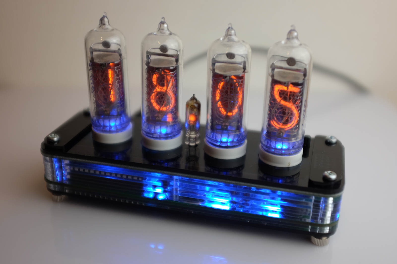
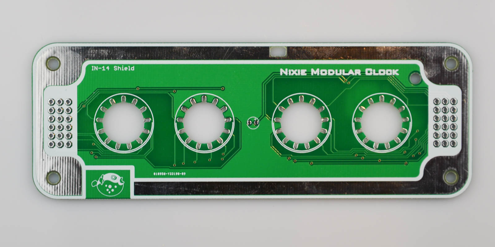
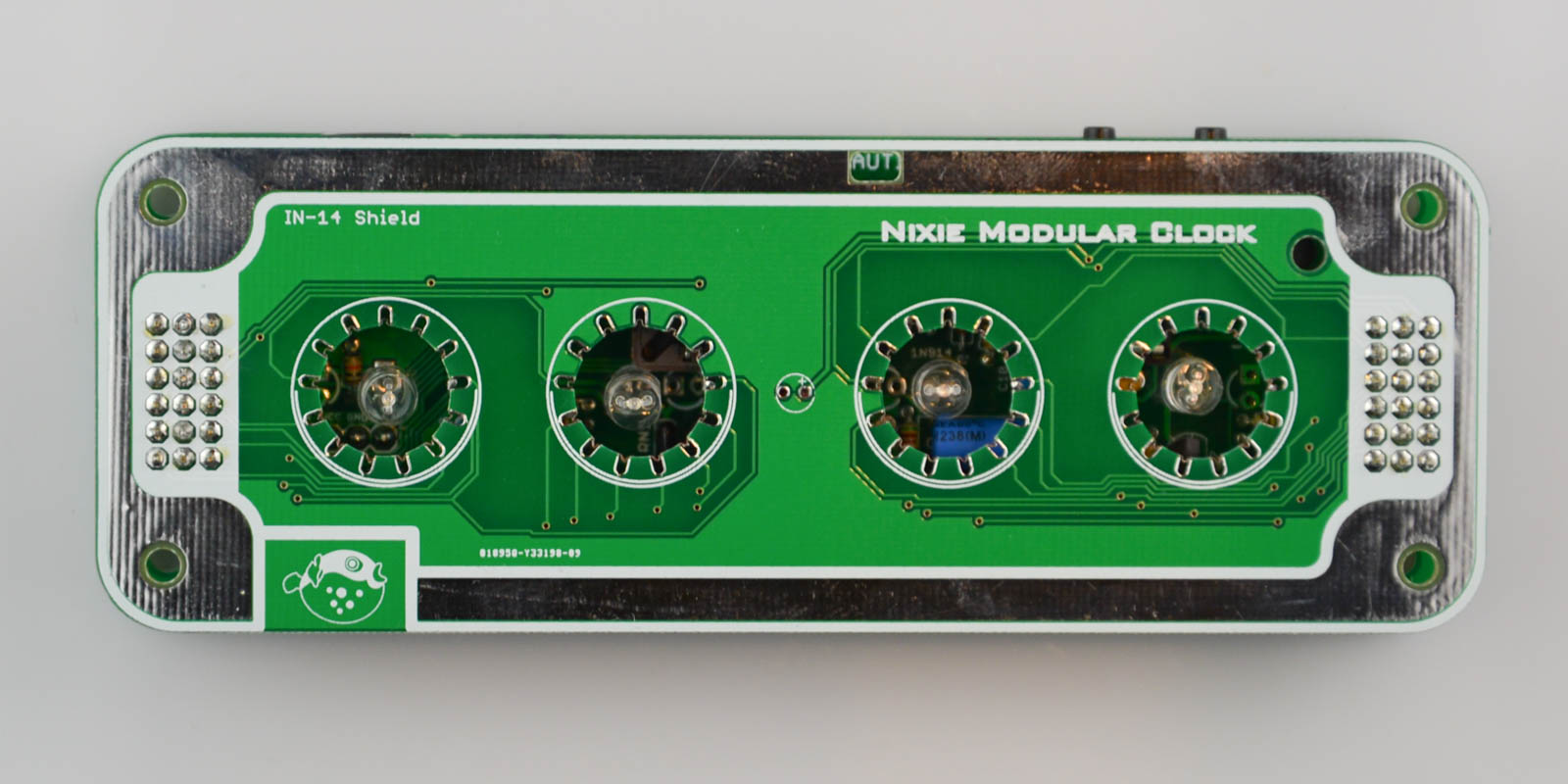
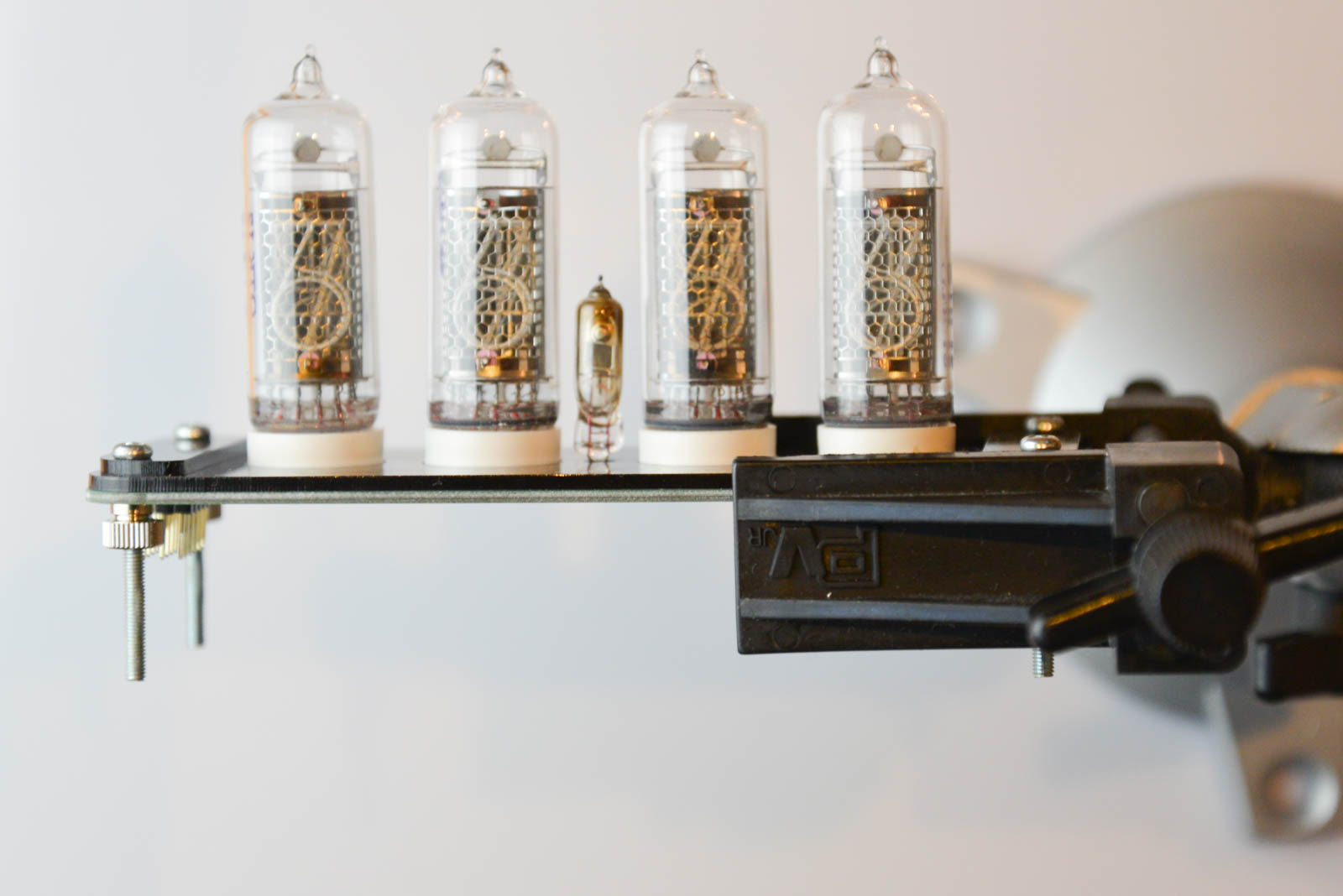
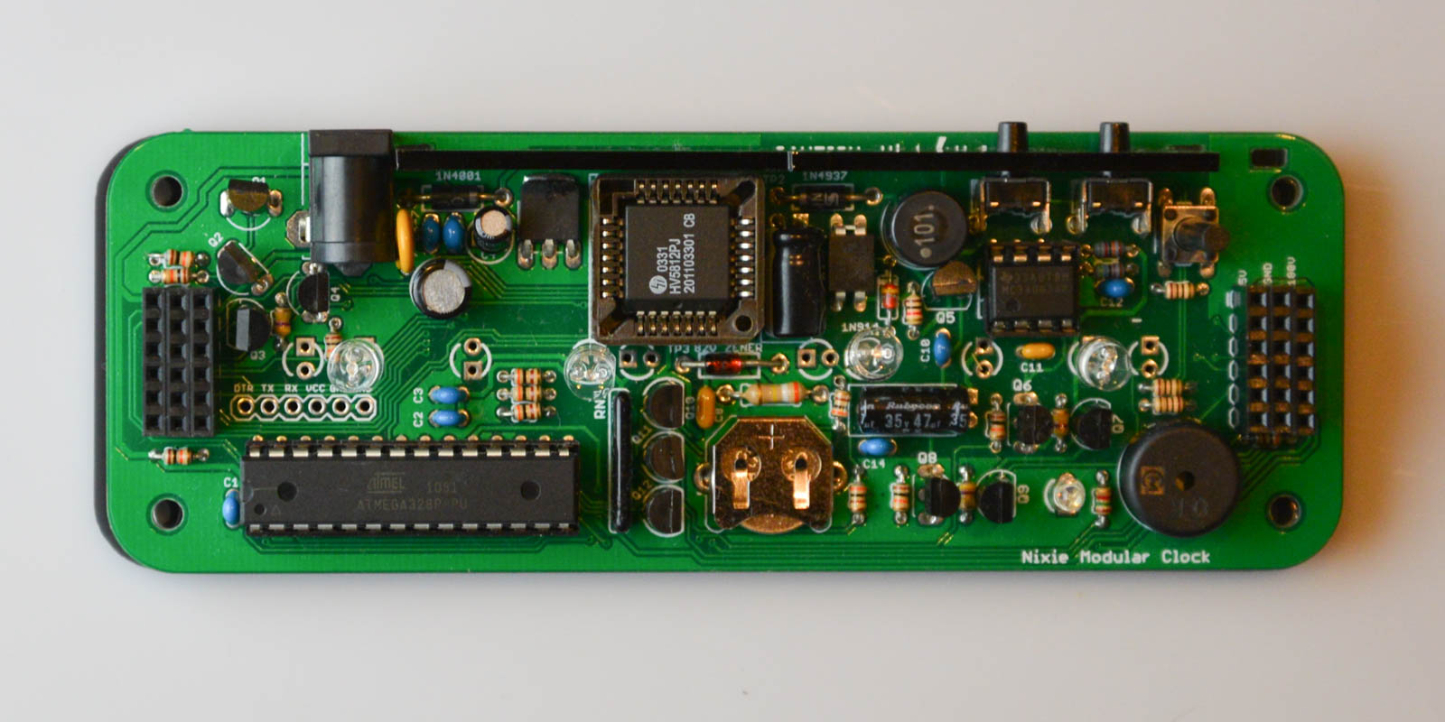
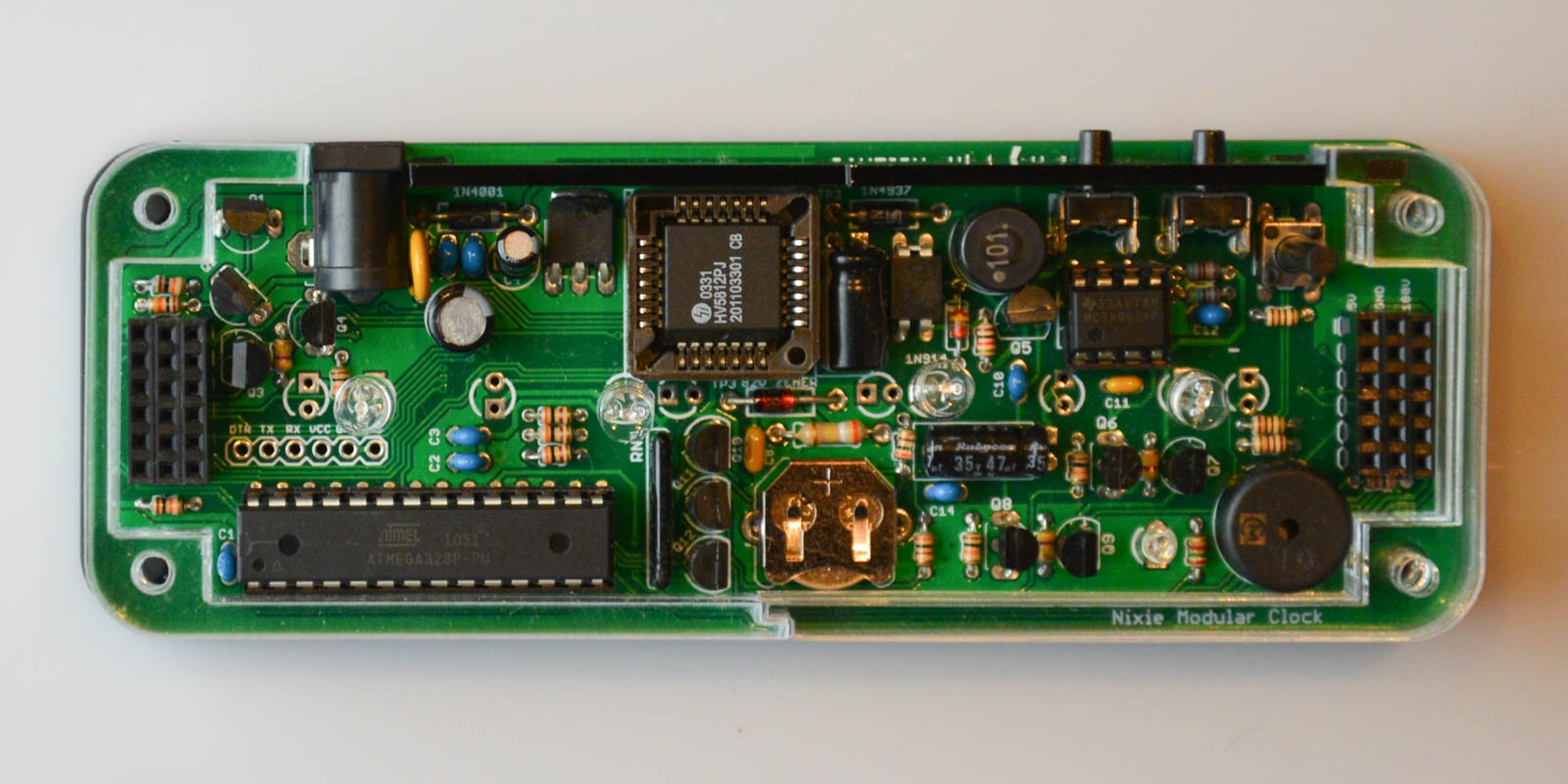
First, take some time to familiarize yourself with the Nixie Modular Clock IN-14 Board:
Parts
- 1x IN-14 Board
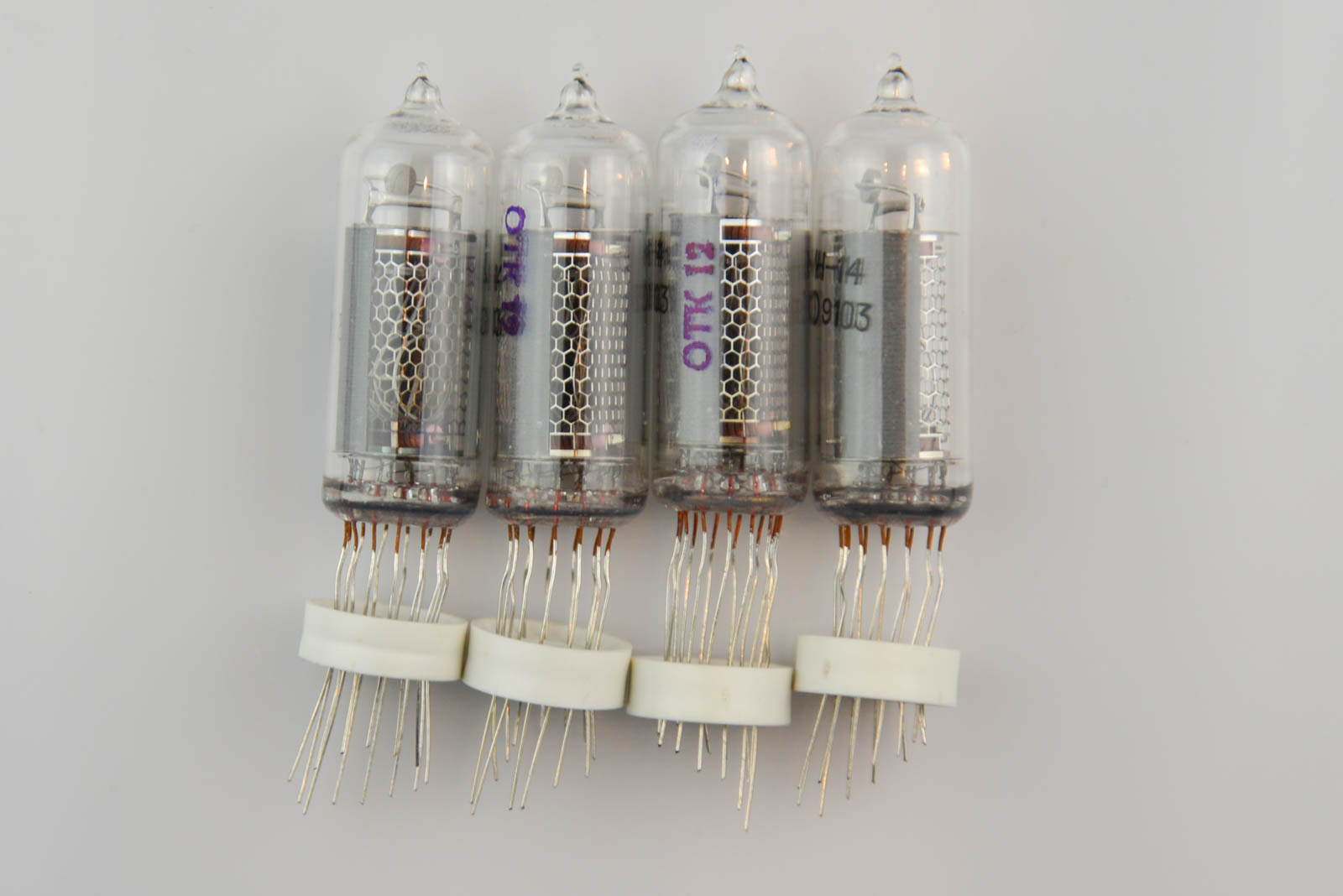
- 4x IN-14 Nixie Tubes
- 1x Neon dot
- 6x 1x6 male pin-header
- 4x Blue 5mm LEDs
Enclosure Parts
- 4x M3x30 screws
- 4x M3 feet
- 1x back plate
- 1x bottom plate (gray)
- 1x bottom plate (transparent)
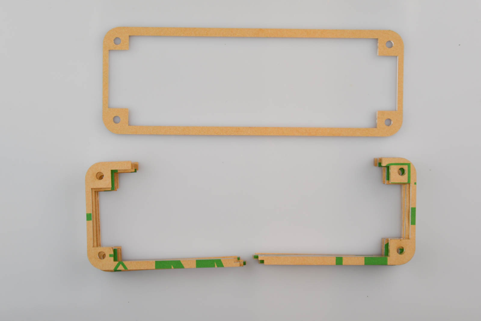
- 4x left side plates
- 4x right side plates
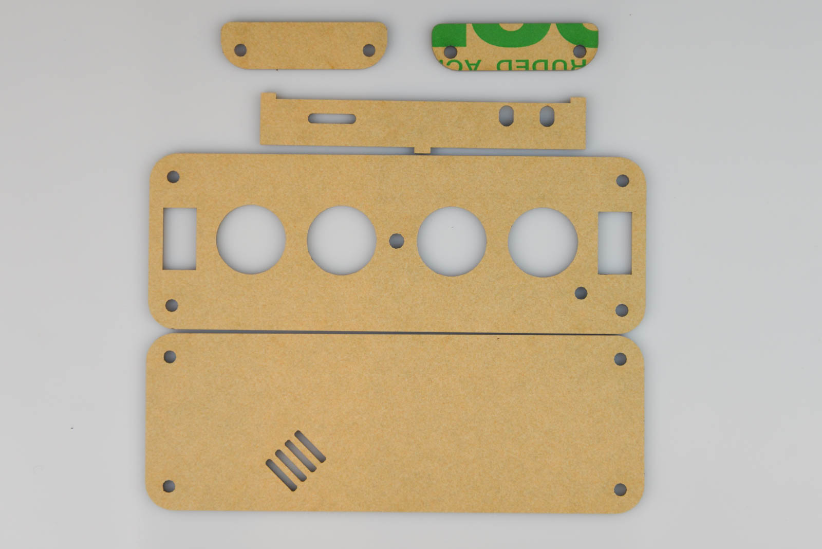
- 1x top plate
- 1x top plate (left)
- 1x top plate (right)
You must peel off the protective paper on the acrylic parts before using them.
Assembly
Note: These instructions are still under construction. If anything is unclear, don't hesitate to contact us by email.
Step 1
First place the six 1x6 male headers into the base board's female 3x6 connectors. The long part goes down. Place the IN-14 PCB board on top, so that the writing faces forward. (and the button in the top right goes through the hole.)
Solder all the pads, then lift the board up and away from the base board.
Step 2
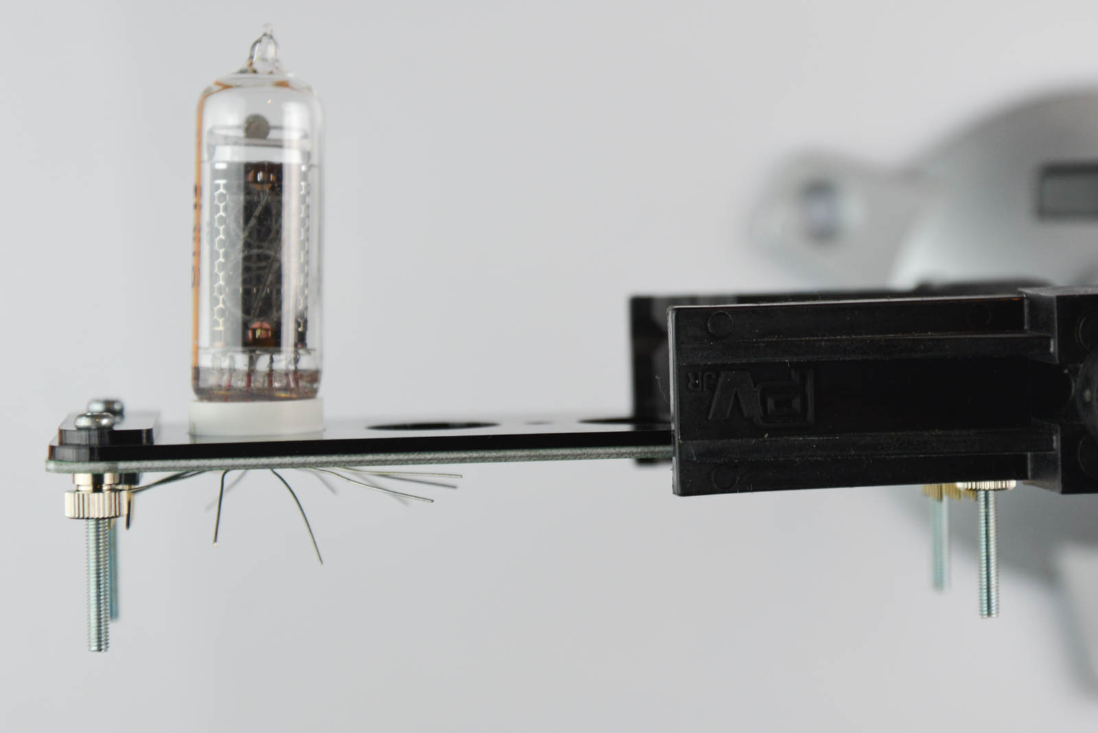
Cut the legs of the IN-14 tubes so that each leg is slightly shorter than the next. Go around the tube and cut off segments of the legs until the pins resemble a V shape.
Once you have done that, carefully remove each base.
In order for the bottom LED light to go shine through to the tube, it is neccesary to drill holes in each base. Be very careful when doing this: Use a low power drill only, otherwise you may melt the plastic.
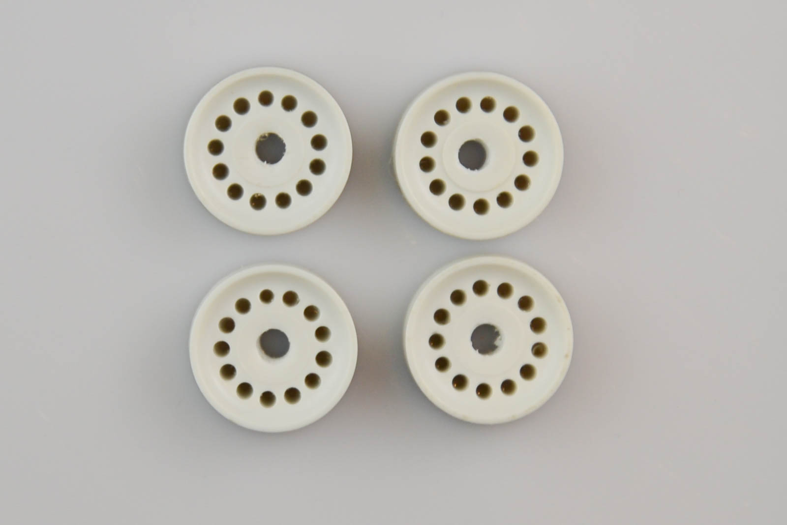
Re-tread the plastic bases of all the tubes.
If you prefer, it is also possible to skip the tube bases altogether, for a different look.
Step 3
Find the acrylic top plate (with four holes for the tubes) and the two small cover plates (smoke gray). Also get the four screws and the metal legs.
Put the top plate and cover plates on top of the PCB, and insert the four screws. Fasthen the screws underneath the board with the metal legs
Step 4
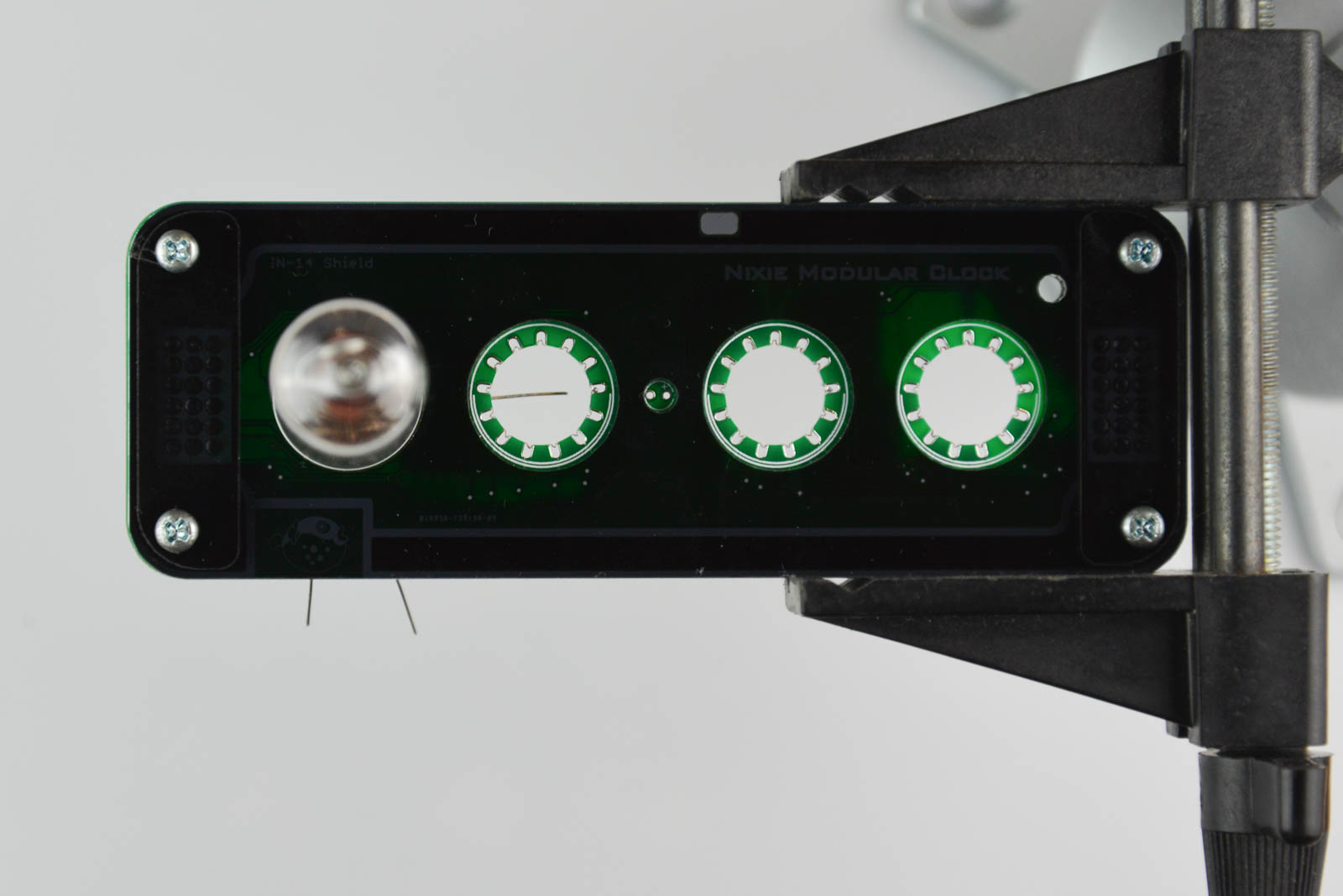
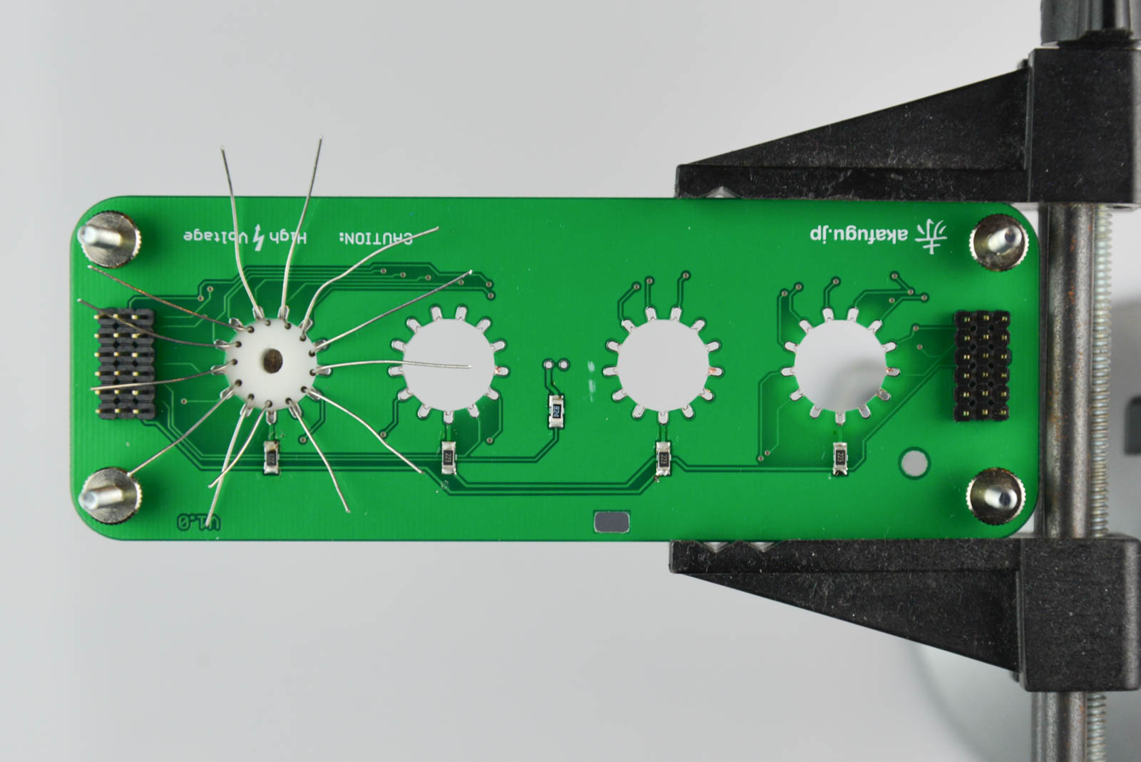
Insert one tube into the hole on the left. Make sure that the wire on the back of the tube (there is a small white dot inside the tube to mark the backmost wire) goes to the hole on the back of the tube footprint.
Insert the tube, and bend the legs outward and pull them so that they fit into their respective holes.
Step 5
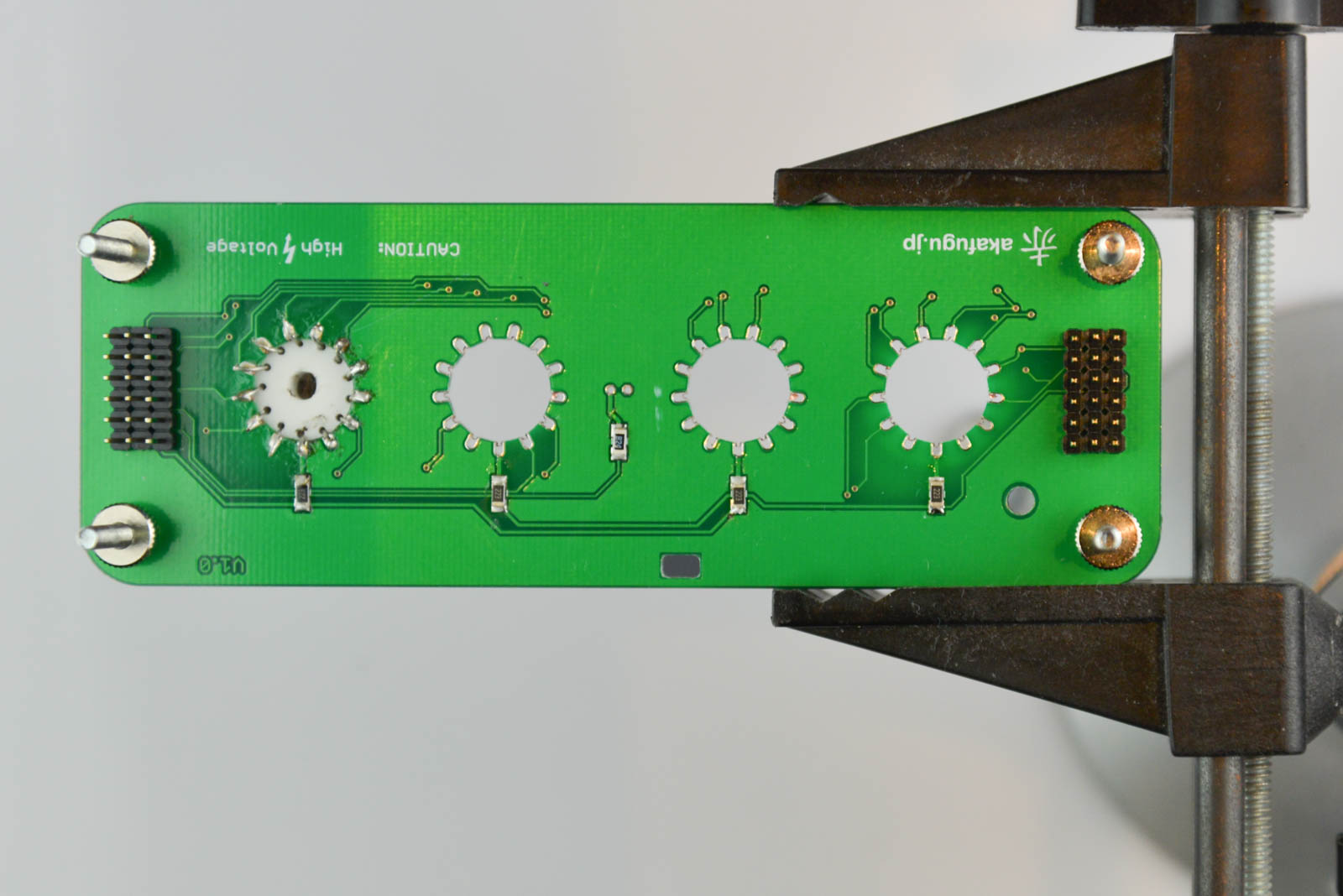
Carefully clip off each leg.
Repeat for the remaining three tubes.
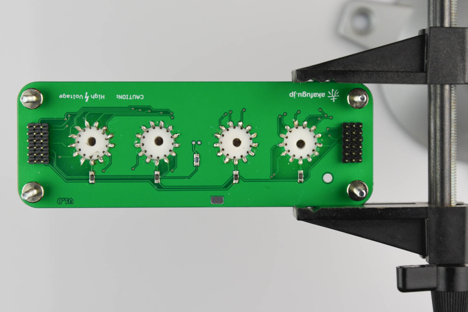
Insert the tube board into the base board and insert power. Check that all the tubes light up correctly.
To put the clock into test mode, hold button 3 (the one that sticks out from the display board) for several seconds. The clock will then start to cycle through each digit, and you can see if you have made any mistakes in the soldering.
Remove power, and then remove the base board from the tube
Step 6
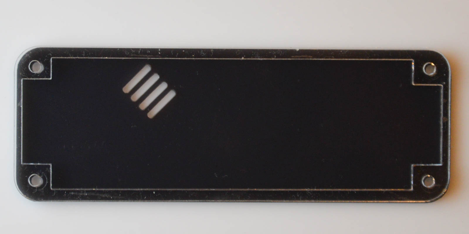
Insert the neon dot. There is an arrow on the base of the glass envelope that indicates polarity. It should point to the RIGHT.
Step 7
Now we finish the case assembly.
First place the bottom board, and the single full transparent layer.
Step 8
Insert the back plate over the buttons. You will need to snap the board into its holes. Place the base board over the acrylic parts from last step.
Step 9
Layer each of the 8 small transparent acrylic plates on the left and right side. Note the difference between the left and right sides.
Step 10
Remove the legs from the display board screws, and carefully place the whole tube board with screws into their respective screw holes, making sure to mate the display board with the base board connectors as you go. This part is a bit fiddly, so go slowly, and make sure not to break any acrylic parts.
Finally, secure the legs underneath the clock: