Assembly Instructions for 2x7 connector
These instructions are for assembly of any display that uses a 2x7 connector:

Compatibility
The 2x7 connector is supported by TWILCD (standard) ONLY.
Connection
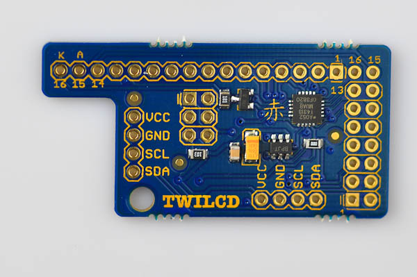
The display should be connected as follows on a TWILCD (standard) board:
If the display has a backlight, look for separate connectors on the display marked A and K. They need to be connected (by pulling wires) as follows:
Please see the compatibility page for an overview of supported displays.
Requirements
To assemble this kit, you will need:
- A soldering iron
- Solder
- A wire cutter (a diagonal type that allows you to cut the wires as close to the soldering points as possible is best)
- Helping hands or clips to hold the PCB in place when soldering (a vise will also work)
- A wire stripper
Optional:
- A multimeter
- Desoldering wick
- Solder sucker
- Protective glasses
See the equipment page for more details.
Step 1
There are two ways in which VCC and GND may be connected on a display with a 2x7 connector. Refer to the data sheet of your device to find out how your display is powered:
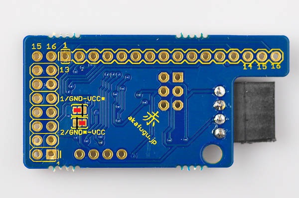
If VCC is on pin 1 and GND on pin 2, you do not need to make further adjustments.
If VCC is on pin 2 and GND on pin 1, it is neccesary to make an adjustment to the back of the TWILCD PCB. Cut the two traces as marked, and bridge the two points as shown:
Step 2
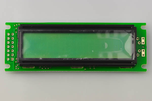
Here is how a typical 2x7 header display looks:
Insert a 2x14 row male header into the display as follows. The long part of the legs should point out and the short part should go into the holes to be soldered in place.
Use a clip or a piece of masking tape to hold it in place, flip the board over, solder in one pin, then check orientation. Once orientation is ok, solder in all the remaining pins.
Step 3
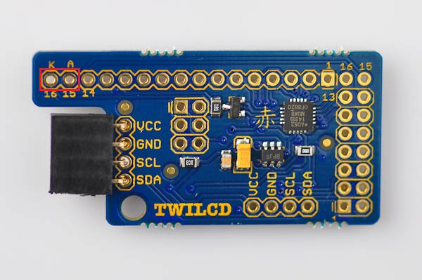
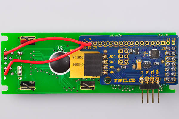
To connect the backlight, you will need two short wires. Solder one in the pin marked K and one in the pin marked A.
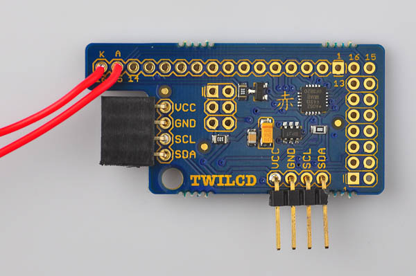
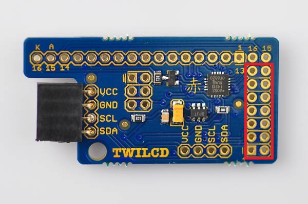
Now insert the board to the back of the display like so and solder all the pins. Note that the top two pins marked 15 and 16 are left open.
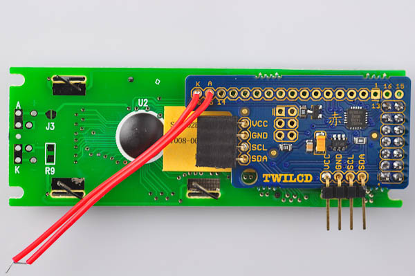
Next, locate the holes on the display marked K and A. The wire attached to the pin marked K on the TWILCD board goes to K on the display, and A goes to A.
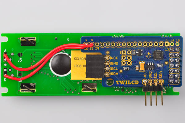
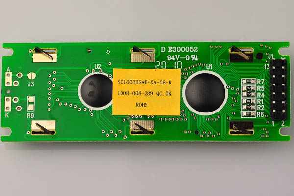
Finally: For the pictured display (a Sunlike 1602B) it is neccesary to add solder bridges marked J3 and R9. This may not be neccesary for your display.
R9 is hard to bridge using only solder. You may want to cut off a tiny piece of bare wire or the leg of a resistor and put on top. This will make bridging easier.
Step 4
Finishing touches: The pins from the header that attaches the display to the TWILCD board stick out a bit. You may want to clip them off (close to the solder point) before using the display. When doing this step hold your hand over each pin as you clip it and use eye protection as small pieces of metal may fly out at very high velocity.
Congratulations, you have now assembled the TWILCD display. Head over to the Usage page for further instructions.