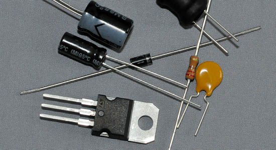
We've put together a kit of useful components to have around when you're just getting started with electronics. It contains the following:
- A set of commonly used capacitors (five different values, 10 items of each)
- Two PTC fuses
- One 7805 regulator
- A set of 20 red 5mm LEDs
- One red 7-segment common anode display
- 10 1N4001 Protection diodes
- One Piezo
PS: If you don't already have resistors, we suggest getting this kit together with the Resistor Starter Kit
Here is a detailed rundown of the contents:
22pF Ceramic Capacitor Commonly used with crystals. If for instance you want to connect a 16MHz crystal to an ATMega chip, you'll need two of these capacitors connected.0.1µF Ceramic Capacitor The standard smoothing capacitor for ICs. You will typically put one of these per IC in you circuit to smooth out voltage spikes. Put it as close to the chip it is decoupling as possible.10µF Electrolytic Capacitor A common smoothing capacitor for when you do not need very big power reserves. If you use USB 5V to get regulated power to your circuit, putting in a 0.1µF along with a 10µF is a good idea.47µF Electrolytic Capacitor Commonly used together with a voltage regulator to smooth out any voltage spikes. Typically, you put one of these on each side of the regulator, together with a 0.1uF on each side.
100µF Electrolytic Capacitor
Whether you want to use a 47uF or a 100uF depends on how much power your circuit draws. In most cases, 47uF is a good choice.
PTCWhen prototyping you will sooner or later find that you have shorted something out. If you're unlucky, this can damage your components. The simplest way to guard against this is to put a PTC in your circuit. If you have regulated power coming in, just put one in series on the input voltage line. You will see a small voltage drop, but this is usually not a problem. When using a voltage regulator, place the ptc between the power input and the input leg of the regulator.
PTCs can look very similar to Ceramic Capacitors. To make it easy to distinguish them, the kit contains blue Capacitors and Orange PTCs.
7805 regulator
The most common component used to get a nice steady 5V supply. Use together with smoothing capacitors. A 5V wall-wart power supply is usually not regulated, meaning that depending on how much current you draw the actual voltage changes. For some circuits this is ok, but it can damage microcontrollers.
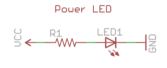
LED
Making a LED blink is the entrypoint for almost all microcontroller tutorials, and you will definitely want some LEDs around to use as indicators. You will need a current-limiting resistor in series with the LED, otherwise it will burn out. 220 ohm is a good choice, or something higher if that is too bright.
7-segment common anode display.
Playing around with controlling a single digit 7-segment display is a nice way to learn about output pins on a microcontroller. Connect the common anode pin to 5V, then attach each of the 8 segment pins through a current-limiting resistor to microcontroller pins. To make a segment light up, pull the pin LOW, to shut it off, pull the pin HIGH.
Tactile switchIf you need to add user input, this is the easiest way. Be sure to add resistors.
1N4001 diodeA diode blocks current in one direction and conducts in the other. The 1N4001 is a general purpose diode that can take up to 1A of current.
PiezoAn easy way to add sound. Connect one pin to ground and the other to a PWM pin on your microcontroller. Changing the PWM duty cycle changes the tone played.