Assembly Instructions
The PCB comes pre-assembled, but the headers that plug into the breadboard and the serial port are not attached. These must be soldered on before use.
Requirements
To assemble this kit, you will need:
- A soldering iron
- Solder
Optional:
- A multimeter
- A wire cutter (a diagonal type that allows you to cut the wires as close to the soldering points as possible is best)
- Helping hands or clips to hold the PCB in place when soldering (a vise will also work)
- Desoldering wick
- Solder sucker
- Protective glasses
See the equipment page for more details.
Step 1
Break off the header strip into two 14-pin and one 6-pin lengths as shown:
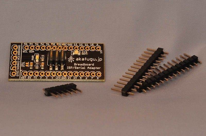
If you are careful, you can break the header strip using your hands, but using a wire clipper is easier.
Step 2
Place the two 14-pin header strips into the breadboard:
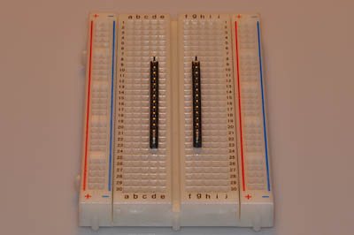
The long part of the legs should point downward.
Step 3
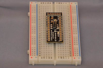
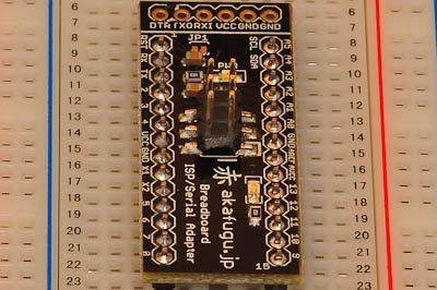
Place the PCB over the two rows of 24 pins. If the pins are aligned correctly, it should slide down easily. Press gently against all sides to ensure that it fits snugly.
Step 4
Start by soldering two of the end pins, for instance the top right and bottom left pin:
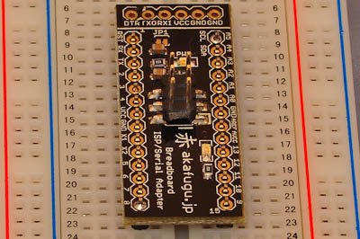
Make sure that the PCB lies flat against the pins, if not, re-apply heat to the soldered points while pressing gently on the PCB.
Step 5
Solder all the remaining points.
Step 6
Carefully remove the PCB from the breadboard. It will usually stick quite firmly, so be sure to pull it out slowly and evenly to avoid bending any legs.
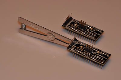
Now rest the PCB with the legs pointing downward on your workbench, and place the 6-pin header into the 6 pins on top, short pins should point downward so that the FTDI adapter can be inserted from the top.
You will need to hold the header in place while you turn the board over to solder the six remaining points from underneath. There are many ways to accomplish this: Attaching a clip in the middle and then attaching the PCB to a set of helping hands is probably the easiest.
If you dont have clips, you can use masking tape to temporarily hold the header in place while soldering it.
Whichever way you use to hold the header in place: Be sure to solder just one leg first. This way, you can re-apply heat and adjust the position if the header is not properly aligned. This is very difficult to do if you solder all six points at once.
Once you are satisfied with your first solder point solder the remaining five points.
Congratulations! You have assembled the Serial and ISP Adapter.