Assembly Instructions
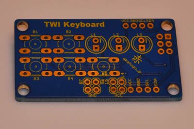
The TWI Keyboard comes partially assembled: The main processor (an ATTiny2313) and supporting surface mount components are all soldered on.
The rest of components must be soldered before use.
Step 1
Turn the PCB so that the side with the processor faces down.
Step 2
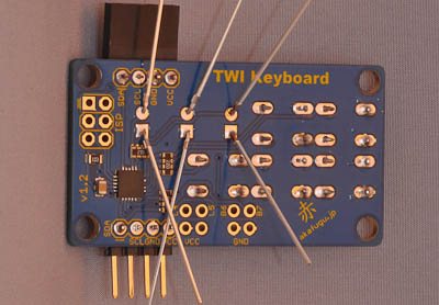
Insert the 4-pin female header and the 4-pin male header as shown:
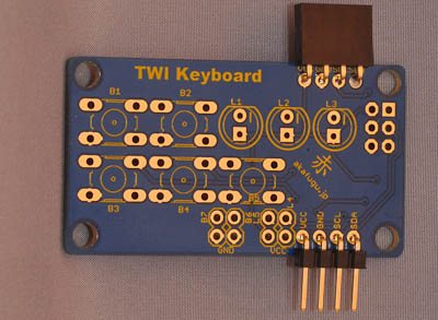
They will need to be fastened so that they stay in place while you solder them. The easiest way is to use clips. If you only have one clip you can solder them one at a time instead of together.
<%= make_note("We recommend putting the female header on top and the male header on the bottom. This way several boards can be daisy chained together if you need more buttons and LEDs." ) %>
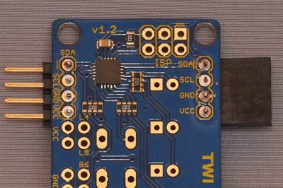
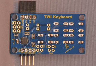
Now turn the board over and solder the headers in place. First solder only one pin and make sure that orientation is correct. If not, re-apply heat and adjust the header until you are happy with the orientation. It should point 90 degrees out from the PCB. Once you are happy, solder the remaining pins.
The result should look like this:
Step 3
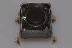
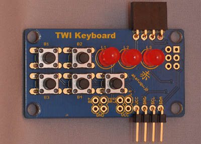
Insert all the buttons. The correct alignment is so that the legs of the button bend inward horizontally. The button will fit more naturally into the PCB this way. Press the buttons all the way in so that they lie flat against the PCB and stick in the hole even if you turn the PCB upside down.
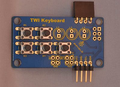
NOTE: If you place the buttons incorrectly, the keyboard will still work properly, but it will not look as natural.
Step 4
Turn the PCB over and solder all the buttons.
Step 5
Now it is time to insert the LEDs. LEDs are polarized and must be inserted the correct way, otherwise they will not work.
The LONG leg of the LED goes into the square unmarked hole. The SHORT leg goes into the round hole with a minus (-) sign next to it.
Push both legs through, and bend them outward on the back side so that they are held in place when you turn the board over to solder them.
Step 6
You can place all three LEDs at once, bend the legs, then turn the board over and solder all six pins. When that is done, use your wire clipper to carefully clip off the excess part of each leg.
<%= make_note( "If you ever want to reprogram the firmware of the display, you can do so using the 6-pin ISP header. You will need to solder a 2x3 pin female header (not included). You will also need an ISP programmer." ) %>
Congratulations! You have now assembled the TWI Keyboard.
Head on to the Usage page for further instructions!