Assembly Instructions
The 5V Breadboard USB Power Supply comes as a kit, and must be assembled before use. It consists entirely of easy to solder Through-the-hole components, and can be assembled by anyone with basic soldering experience.
Requirements
To solder this kit, you will need:
- A soldering iron
- Solder
- A wire cutter (a diagonal type that allows you to cut the wires as close to the soldering points as possible is best)
- A multimeter
Optional:
- Helping hands or a vise to hold the PCB in place when soldering
- Tweezers to help pull the legs of the components through the holes (an angled tweezer is ideal for this)
- Desoldering wick
- Solder sucker
- Protective glasses
See the equipment page for more details.
Step 1
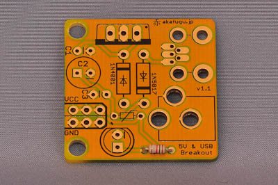
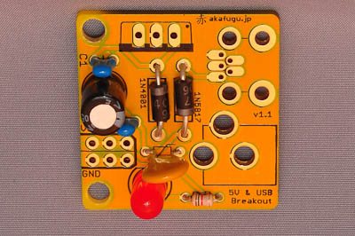
1kΩ (Brown, Black, Red, Gold)Place the 1kΩ resistor in the place marked R1. A resistor is not polarized and can go in any way. Push it in and bend the legs to hold it in place, and then flip it over and carefully solder both legs. Clip off the excess part of the legs after soldering.
Place the resistor into the part marked R1:
Turn the board over, bend the legs outward and solder them:
Finally, clip off the excess part of the legs:
Step 2
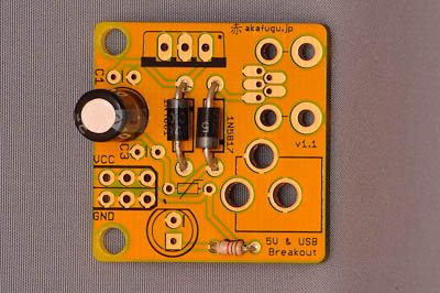
Now its time to place the two diodes. Diodes are polarized and must and it must be put in the right way: The white strip on the diode should line up against the strip on the PCB. Diodes can be a bit hard to push flat against the PCB, so using tweezers to pull on the legs for alignment is helpful here.
There are two diodes: A 1N4001 diode (on the left in the picture) and a 1N5817 (on the right side in the picture.
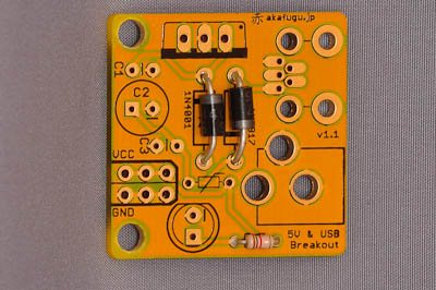
Make sure that the diodes are placed properly: Bend the legs, flip the board and solder in place. Finally, clip the legs.
Step 3
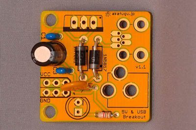
Next, place the 74µF electrolytic capacitor in the space marked C3. Electrolytic capacitors are polarized and must be placed the correct way: The long leg goes into the square hole, and the short leg goes into the round hole marked '-'.
Here is the electrolytic capacitor viewed from the bottom of the board:
Solder the two legs and clip off the excess part of the legs.
Step 4
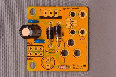
Now place the two 0.1µF capacitors in the places marked C2 and C3. These are also not polarized and can go in any way. Again, push the legs through and bend them to hold in place. Flip over to solder, then clip the legs.
Step 5
The yellow PTC goes between the resistor and the diode. The silk screen has a box with a line through it. The PTC is not polarized and can go in any way.
Bend the legs, flip the board and solder in place. Finally, clip the legs.
Step 6
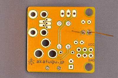
Place the LED in the holes marked PWR. The LED is polarized and must go in the correct way: The long leg goes through the square hole, the short leg goes through the round hole.
Pull the pins through, and bend the legs the hold them in place. Finally solder the pins and clip off the excess part of the leg.
Step 7
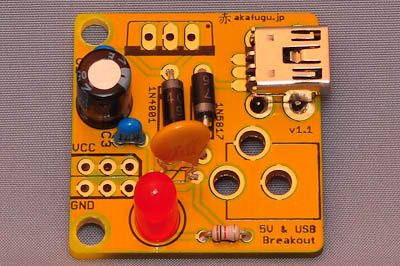
Now it is time to place the USB mini-B connector: It will only fit one way.
Use clips or a few strips of masking tape to hold the connector in place before you flip over the board to solder it. Solder just one leg first and check that alignment is good before soldering the remaining legs.
Step 8
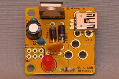
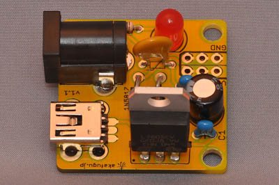
Place the 7805 regulator. It is polarized, and must be put in the way indicated on the silk screen: The silver tab of the regulator should align with the black line on the PCB silk screen.
To hold it in place while soldering, bend two of the legs in one direction and the middle leg in the opposite direction.
Step 9
Place the 2.1mm power jack. It will only fit the correct way. The legs will not bend, so it must be fastened before you can turn the PCB over to solder it. A couple of strips of masking tape will do, or clips if you have any that are large enough.
Solder one leg first and make sure the alignment is good. If not, re-apply heat and adjust the position until you are happy. Then solder the remaining legs: The holes are big and will require quite a bit of solder. Beware: The surrounding area will become very hot, so let it cool down a bit before touching anything.
Step 10
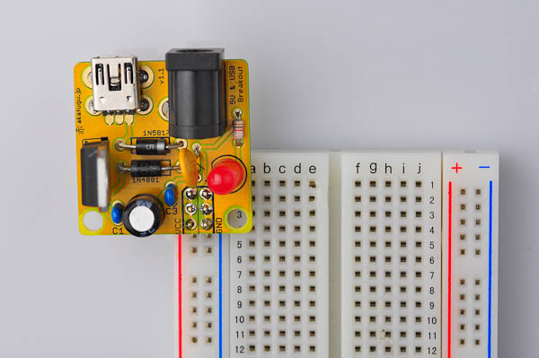
The final step is to place the 2x3 male header.
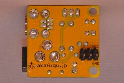
To use the 5V and USB power supply with a breadboard, the header should be placed on the bottom side of the PCB (on the side that has no other components).
Place the 2x3 male header into a breadboard so that the long part of the legs point downward into the breadboard. Now place the PCB on top.
Solder one leg first and adjust alignment until the board lies flat against the header. Once you are happy, solder the remaining legs.
(It is also possible to use the board as a general power supply: Just solder wire directly on the VCC and GND pins as required)
Before usage, be sure to use a multimeter to check that the voltage is proper: The voltage will be a bit less than 5V regardless of whether you use the USB plug or the power jack. This is because both power routes go through the PTC fuse to protect against short circuits.
Congratulations! The 5V and USB power supply is not assembled and ready for use.
Head on to the Usage page for further instructions!