Overview
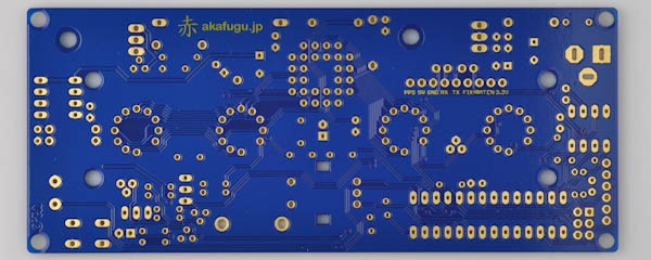
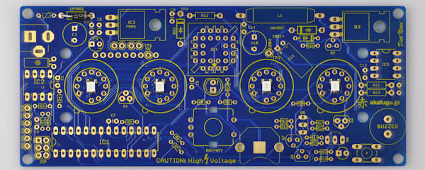
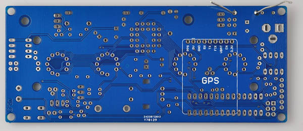
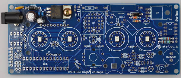
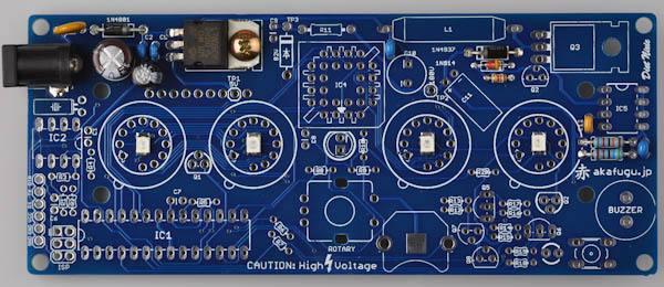
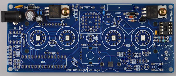
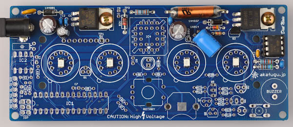
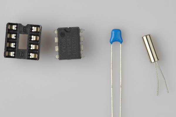
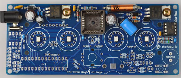
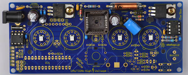
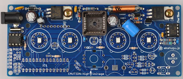
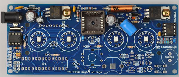
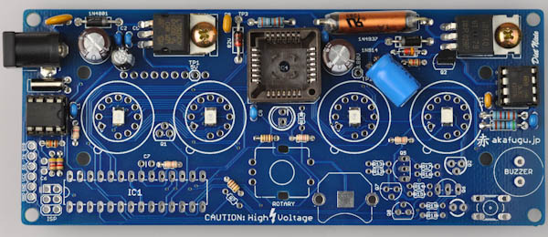
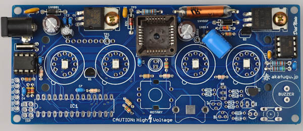
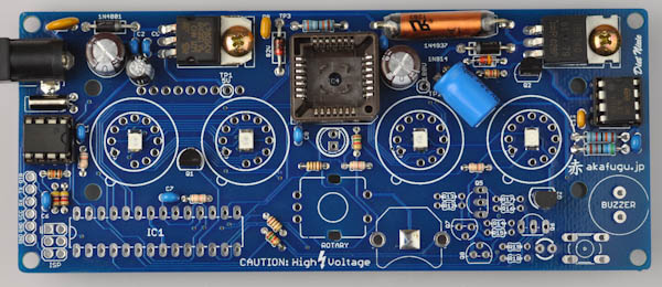
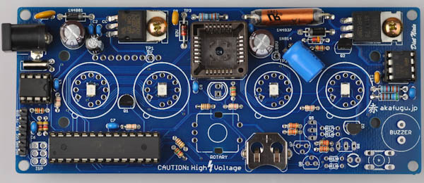
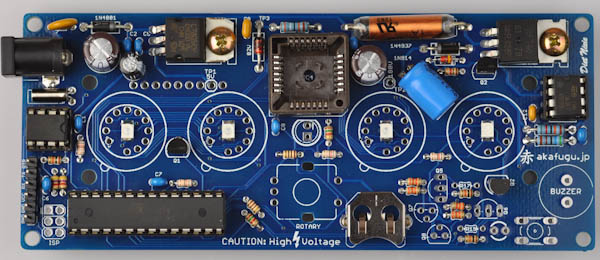
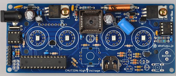
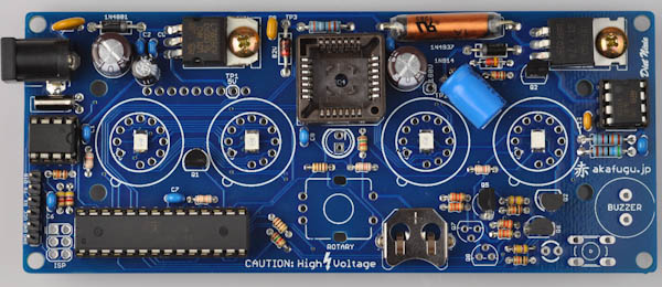
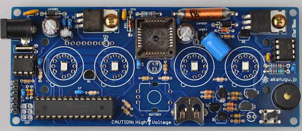
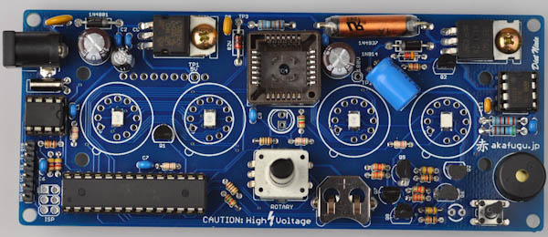
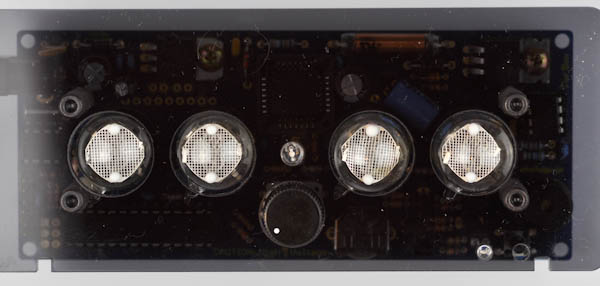
First, take some time to familiarize yourself with the Diet Nixie PCB board:
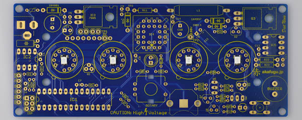
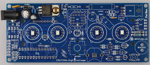
We will assemble the Diet Nixie in a way that makes it easy to test that everything is working correctly along the way.
PART 1 - 5V Power Supply
We will assemble the components required for the 5V power supply first. This is the part of the circuit that takes the 9V input voltage and produces a nice stable 5V voltage that the microcontroller and the other perhiperals run off.
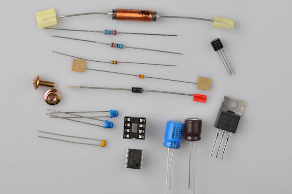
Required Components
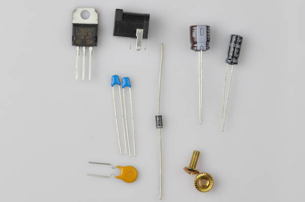
- 1x 2.1mm Power Jack
- 1x PTC fuse
- 1x 1N4001 diode
- 1x 47µF Electrolytic Capacitor (brown) (C3)
- 1x 47µF Electrolytic Capacitor (small black) (C4)
- 2x 0.1µF Ceramic Capacitors (small blue) (C2, C5)
- 1x 7805 Voltage Regulator
- 1x Screw
- 1x Nut
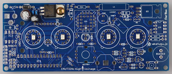
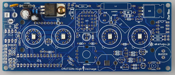
Step 1a
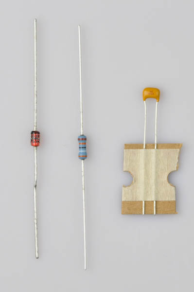
We'll start by inserting the 1N4001 diode in the footprint marked 1N4001 on the top left hand side of the PCB. There are several diodes, make sure you select the correct one.
It is black with a white stripe (there are two diodes like this). 1N4001 is written on the side.
Bend the legs of the diode 90 degrees to make it easy to insert. Take note of the white stripe on the diode: Orientation is important and it must be inserted so that the white stripe on the diode lines up with the white stripe on the PCB footprint.
After it is inserted properly (pull the legs with pinchers if you have trouble making the diode lie evenly against the PCB), bend the legs outward slightly.
Turn the board over and solder the two legs.
Clip off the excess part of the legs with a flat wire clipper.
Most of the other two-legged parts, such as resistors, capacitors and other diodes are soldered using the same technique.
Step 1b
Next, place two of the blue 0.1µF ceramic capacitors into C2 and C5. Bend the legs to keep it in place, just like the diode.
Ceramic Capacitors are not polarized and can go in any way.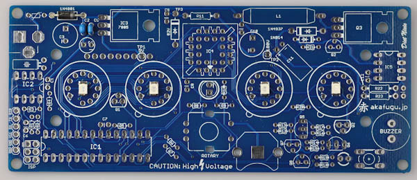
Step 1c
Now, place one of the brown 47µF electrolytic capacitors (C3).
Electrolytic Capacitors are polarized and must be inserted the correct way. The long leg goes in the square hole. The short leg goes in the round hole (marked with a minus sign)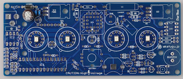
Step 1d
Next up is the smaller black 47µF electrolytic capacitor (C4).
Electrolytic Capacitors are polarized and must be inserted the correct way. The long leg goes in the square hole. The short leg goes in the round hole (marked with a minus sign)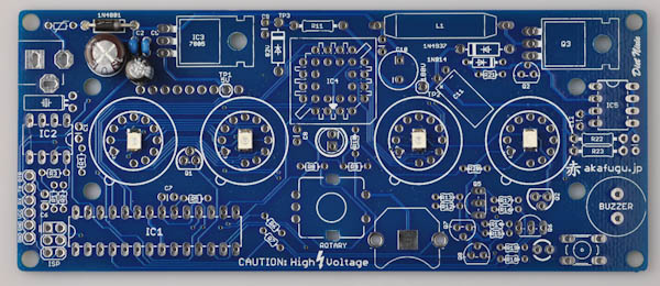
Step 1e
Locate the 7805 5V regulator, it goes to IC3. Bend the legs 90 degrees and insert it so that the hole lines up with the hole in the PCB.
Place the nut and screw before soldering. Once it is secured, solder all three legs and clip off carefully.
Step 1f
Now it is time for the PTC fuse. It is a large yellow disc with two legs. The kit also includes two smaller yellow ceramic capacitors, so make sure not to mix them up.
Orientation doesn't matter for this component.
Step 1g
Time for the 2.1mm power jack connector. Insert it so that the hole points outward as in the picture. If it doesn't stay in place when you turn the board over, keep it in place with some masking tape.
Solder only one leg first, then check that the orientation of the component is correct. If not, re-apply heat and adjust as neccesary. Once you are happy with the orientation, solder the remaining legs.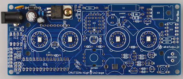
Step 1f - Testing the 5V supply
Insert the power jack of the 9V power supply and then plug it in to the wall outlet. Locate your multimeter and set it to DC voltage metering.
Touch the black probe to one of the holes on the bottom left side of the PCB marked GND.
Touch the red pad to the point marked TP1, underneath the voltage regulator.
The multimeter should now read aproximately 5V. Remove the power jack from the device.
If the voltage was not correct, go back and double-check all component placement and solder points. Gently touch the yellow PTC fuse: If it is hot, it indicates that there is a short somewhere on the board.
DO NOT PROCEED TO PART 2 BEFORE YOU ARE ABLE TO VERIFY THAT THE 5V SUPPLY WORKS CORRECTLY.
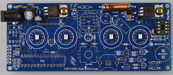
PART 2 - 180V Power Supply
Now that we've verified that the 5V power supply works correctly, we'll continue on to the 180V power supply. The Nixie tubes need 180V to run, which is created by a DC/DC converter from the 9V input voltage.
IMPORTANT: Once this step is finished, whenever you apply power to the board it will generate 180V DC voltage. Be sure never to touch the board or work on it when power is applied. Always remove the power connector before doing anything else!
Required Components
- 1x DIP-8 socket
- 1x MC34063 DC-DC converter
- 2x 0.1µF Ceramic capacitors (small blue) (C13, C14)
- 1x 470pF Ceramic capacitor (small yellow) (C12)
- 1x IRF740 MOSFET
- 1x Screw
- 1x Nut
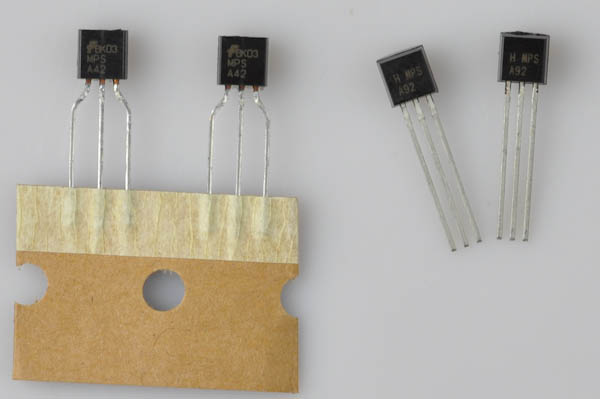
- 1x MPSA55 Transistor (number marked on transistor)
- 1x 1N914 Diode (small red and yellow diode)
- 1x 1N4937 Diode(black, number marked on diode)
- 1x 2.2µF/250V Electrolytic Capacitor (blue)
- 1x 47µF Electrolytic Capacitor (blue)
- 1x 100uH Inductor (coil)
- 1x 1kΩ (Brown, Black, Red, Gold) 1/6W (R21)
- 1x 820kΩ (Gray, Red, Yellow, Gold) 1/4W blue (R22)
- 1x 5.6kΩ (Green, Blue, Red, Gold) 1/4W blue (R23)
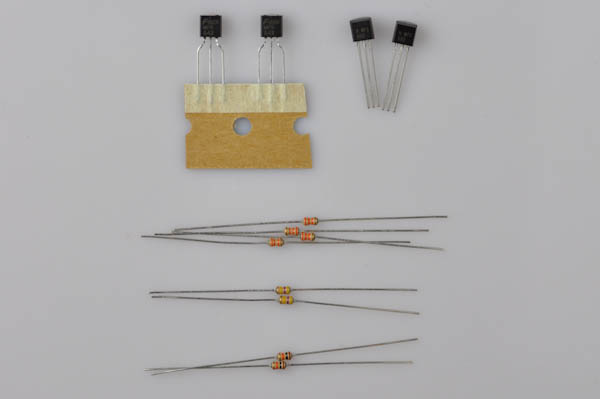
Step 2a
Start by placing the resistors:
- 1x 1kΩ (Brown, Black, Red, Gold) 1/6W (R21)
- 1x 820kΩ (Gray, Red, Yellow, Gold) 1/4W blue (R22)
- 1x 5.6kΩ (Green, Blue, Red, Gold) 1/4W blue (R23)
If you are in doubt about the values, double check with a multimeter. R22 and R23 set the output voltage of the DC/DC converter to produce 180V. Make sure not to mix them up, or the output voltage will be wrong!
Step 2b
Next, we will place the 1N4937 and 1N914. The 1N4397 is black with a white stripe and has 1N4397 written on the side. The 1N914 diode is smaller and is red with a yellow stripe.
Make sure the stripes line up with the stripes on the PCB. The footprints are in the upper right area of the PCB.
Step 2c
The next step is to place 3 more ceramic capacitors. This time there are two different kinds:
- 2x 0.1µF Ceramic capacitors (small blue) (C13, C14)
- 1x 470pF Ceramic capacitor (small yellow) (C12)
There are two yellow ceramic capacitors included: The 470pF is the smallest one.
Step 2d
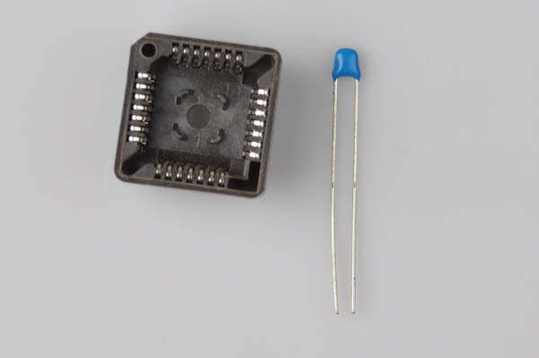
Find one of the 8-pin DIP sockets. Insert it into IC5, so that the half-circle indentation matches the half-circle printed on the PCB footprint.
The component may fall out when you turn the board over to solder. You may use a small piece of masking tape or similar to hold it in place.Solder only one leg first, then check that the orientation of the component is correct. If not, re-apply heat and adjust as neccesary. Once you are happy with the orientation, solder the remaining legs.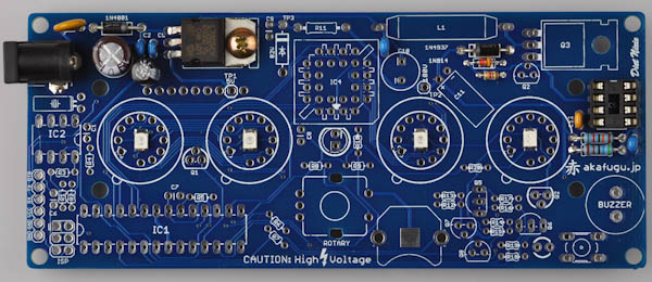
Step 2e
Next up is the MPSA55 transistor. There are many transistors included, so make sure to pick the correct one. It has MPSA55 written on it.
Transistors are polarized and must be inserted the correct way. The half-circle shape of the transistor should match up with the half-circle on the silk screen.Solder only one leg first, then check that the orientation of the component is correct. If not, re-apply heat and adjust as neccesary. Once you are happy with the orientation, solder the remaining legs.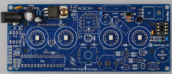
Step 2f
Find the IRF740 MOSFET. It is the same shape as the voltage regulator in part 1. Bend the legs 90 degrees as before, insert, then fasten using the screw and nut. Once it is securely fastened, solder and clip off the legs.
Step 2g
Next is the 100uH inductor. It is the long coil in a plastic enclosure. This part is not polarized and can go in any way.
Step 2h
Now find the remaining brown 47µF electrolytic capacitor.
Electrolytic Capacitors are polarized and must be inserted the correct way. The long leg goes in the square hole. The short leg goes in the round hole (marked with a minus sign)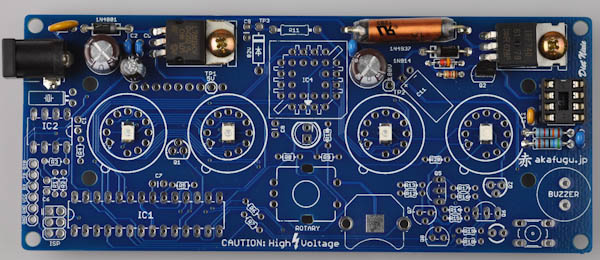
Step 2i
Next is the 2.2µF/250V electrolytic capacitor. Bend the legs 90 degrees before inserting.
Electrolytic Capacitors are polarized and must be inserted the correct way. The long leg goes in the square hole. The short leg goes in the round hole (marked with a minus sign)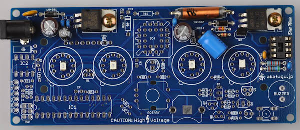
Step 2j
Find the MC34063 8-pin DIP chip. It is marked MC34063 or 063EC.
The IC chip must be fitted in the correct way. The half-circle (or dot) on top of the chip should match the half-circle marking on the silk screen / socket.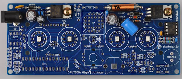
Step 2k
 | WARNING: From now on, whenever you apply power to the board, it will generate 180VDC. Never touch the board while it is powered up. If you touch an area with 180V it will be painful and potentially dangerous! |
Now it is time to test the 180V power supply.
Insert the power jack of the 9V power supply and then plug it in to the wall outlet. Locate your multimeter and set it to DC voltage metering.
Touch the black probe to one of the holes on the bottom left side of the PCB marked GND.
Touch the red pad to the point marked TP2, between the brown and the blue electrolytic capacitors.
The voltage should read about 180V-185V.
DO NOT PROCEED TO PART 3 BEFORE YOU ARE ABLE TO VERIFY THAT THE 180V SUPPLY WORKS CORRECTLY.
PART 3 - 82V Power Supply
The next step is to add the parts required for the 82V power supply. This power supply is derived from the 180V power supply from the previous step. It is used to drive the HV5812 driver used to drive the Nixie cathodes.
Required Components
- 1x 0.1µF/100V Yellow Ceramic Capacitor (C9)
- 1x 82V Zener Diode
- 1x 390kΩ (Orange, White, Yellow, Gold) Resistor (R11)
- 1x 0.1µF Blue Ceramic Capacitor (C8)
- 1x PLCC-28 socket (IC4)
Step 3a
Solder the 390kΩ (Orange, White, Yellow, Gold) to R11 (top middle).
Step 3b
Next is the 82V Zener diode (the final remaining diode). Make sure the black stripe lines up with the white stripe on the PCB footprint.
Step 3c
Now it is time for the two 0.1µF ceramic capacitors. The yellow one goes into C9, and the blue one into C8.
Ceramic Capacitors are not polarized and can go in any way.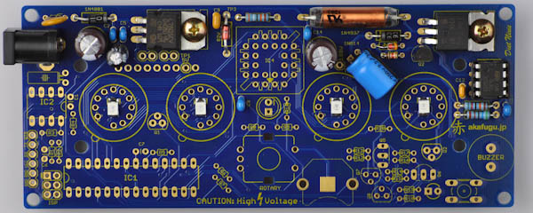
Step 3d
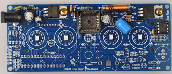
Find the PLCC-28 socket. Insert it so that the shape matches that of the PCB footprint.
The component may fall out when you turn the board over to solder. You may use a small piece of masking tape or similar to hold it in place.Solder only one leg first, then check that the orientation of the component is correct. If not, re-apply heat and adjust as neccesary. Once you are happy with the orientation, solder the remaining legs.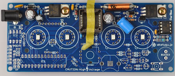
Step 3e
Now it is time to test the 82V power supply.
Insert the power jack of the 9V power supply and then plug it in to the wall outlet. Locate your multimeter and set it to DC voltage metering.
Touch the black probe to one of the holes on the bottom left side of the PCB marked GND.
Touch the red pad to the point marked TP3, located in the middle top of the PCB.
The voltage should read around 78-84V.
DO NOT PROCEED TO PART 2 BEFORE YOU ARE ABLE TO VERIFY THAT THE 82V SUPPLY WORKS CORRECTLY.
PART 4 - Real Time Clock
The Real Time Clock (RTC) keeps accurate time for the clock. It has a backup battery that allows it to keep time even when the main power is removed.
Required Components
- 1x 32kHz Crystal
- 1x DIP-8 Socket
- 1x 0.1µF ceramic capacitor blue (C1)
Step 4a
Insert the blue ceramic capacitor into C1.
Ceramic Capacitors are not polarized and can go in any way.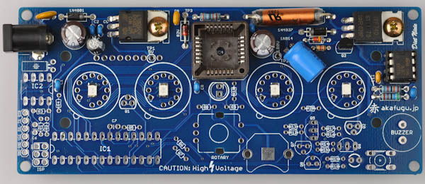
Step 4b
Now find the 32kHz crystal and bend the legs 90 degrees. Insert it into the footprint right beneath the power jack. Orientation of the legs does not matter.
Step 4c
Find the remaining 8-pin DIP socket. Insert it into IC2, so that the half-circle indentation matches the half-circle printed on the PCB footprint.
The component may fall out when you turn the board over to solder. You may use a small piece of masking tape or similar to hold it in place.Solder only one leg first, then check that the orientation of the component is correct. If not, re-apply heat and adjust as neccesary. Once you are happy with the orientation, solder the remaining legs.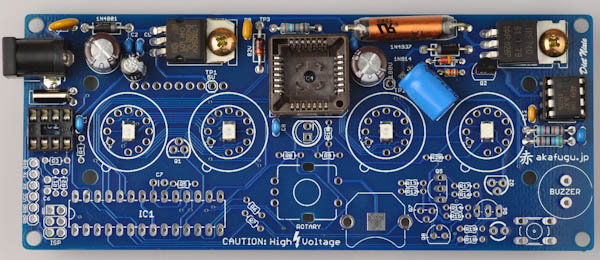
Step 4d
Find the DS1307 8-pin DIP chip.
The IC chip must be fitted in the correct way. The half-circle (or dot) on top of the chip should match the half-circle marking on the silk screen / socket.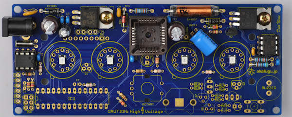
There is nothing particular to test in this part. Proceed to part 5.
PART 5 - Misc Resistors
Diet Nixie requires a large amount of different resistors. In this step we'll place a lot of them.
Be very careful to place all the resistors correctly according to value. Incorrect placement will lead to malfunction.
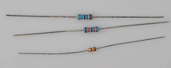
As before, the resistors can be identified by the color of the stripes, but when in doubt always double-check with a multimeter.
Required Components
- 4x 82Ω (Gray, Red, Black, Gold) (R4, R5, R9, R20)
- 1x 10kΩ (Brown, Black, Orange, Gold) (R3)
- 2x 4.7kΩ (Yellow, Violet, Red, Gold) (R1, R2)
- 2x 10Ω (Brown, Black, Black, Gold) (R6, R8)
- 2x 3.3kΩ (Orange, Orange, Red, Gold) (R7, R10)
Step 5a
First, find the four 82Ω (Gray, Red, Black, Gold), and place them in R4, R5, R9 and R20.
These resistors are for the backlight LEDs and are located close to the footprint for each Nixie tube.
Step 5b
The 10kΩ (Brown, Black, Orange, Gold) resistor is next: It goes in R3, right underneath the real time clock chip on the left.

Step 5c
The two 4.7kΩ (Yellow, Violet, Red, Gold) go to R1 and R2, underneath the resistor you placed in the previous step.
These two resistors are pull-up resistors for the TWI/I2C bus.
Step 5d
Next are the two 10Ω (Brown, Black, Black, Gold), that go to R6 and R8.
Step 5e
Finally, the 3.3kΩ (Orange, Orange, Red, Gold) resistors go to R7 and R10.
PART 6 - Microcontroller and Misc
Next, we'll place the actual microcontroller and some supporting components
Required Components
- 2x 0.1µF ceramic capacitors (C7, C8)
- 2x 2N7000 transistors (Q1, Q2)
- 1x 28-pin socket
- 1x Atmega328P microcontroller
- 1x Battery holder
Step 6a
First up is to place two more of the blue 0.1µF ceramic capacitors.
Ceramic Capacitors are not polarized and can go in any way.
Step 6b
Now find the two 2N7000 transistors. They go in Q1 and Q2.
Be sure to orient them properly so that the half-circle shape matches that on the PCB footprint.
Step 6c
Next locate the footprint for the battery holder. It is in the lower right area. Melt a small amount of solder against the square pad in the middle: This will help get better contact with the real time clock backup battery.
Step 6d
Now place the battery holder, orient it so that it matches the drawing on the PCB footprint.
The component may fall out when you turn the board over to solder. You may use a small piece of masking tape or similar to hold it in place.This component will become very hot when soldering, so be careful when touching it.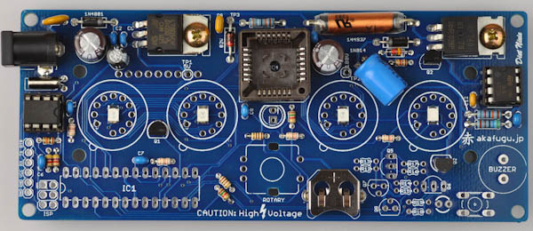
Step 6e
Next up is the 28-pin IC socket, to go into IC1.
Make sure to align it so that the half-circle mark on the socket lines up with the half-circle mark on the PCB (pointing left).
The component may fall out when you turn the board over to solder. You may use a small piece of masking tape or similar to hold it in place.
Step 6f
Find the 6-pin male header, and insert it to the header on the left-hand side. Make sure that the longer part of the legs point upward.
Step 6g
Now place the microcontroller in the 28-pin header. Make sure the the half-circle indentation on the microcontroller lines up with the half- circle on the socket.
Solder only one leg first, then check that the orientation of the component is correct. If not, re-apply heat and adjust as neccesary. Once you are happy with the orientation, solder the remaining legs.
PART 7 - Nixie Anode Drivers
Next, let us place the high voltage transistors and matching resistors used to drive the Nixie Anodes.
Required Components
- 4x 33kΩ (Orange, Orange, Orange, Gold) (R12, R13, R14, R15)
- 2x 10kΩ (Brown, Black, Orange, Gold) (R16, R18)
- 2x 470kΩ (Yellow, Violet, Yellow, Gold) (R17, R19)
- 2x MPSA92 transistor (Q5, Q6)
- 2x MPSA42 transistor (Q7, Q8)
Step 7a
Start with the four 33kΩ (Orange, Orange, Orange, Gold) resistors. They go to R12, R13, R14 and R15.
Step 7b
Next are the two 10kΩ (Brown, Black, Orange, Gold), they go in R16 and R18.
Step 7c
Finally, the remaining two 470kΩ (Yellow, Violet, Yellow, Gold) go in R17 and R19.
Step 7d
The two MPSA42 transistors are next. The legs of these transistors are spaced further apart than the MPSA92 transistors. Also, they have MPSA42 printed on them.
They go to the matching footprints that have three holes in a row, and must be oriented so that the half-circle shape matches that on the PCB silkscreen.
Step 7e
Next are the two MPSA92, they have the number printed on them. They go in Q7 and Q8. Be sure that orientation is correct.
PART 8 - Buttons, Rotary, Piezo and Driver
It is time for the remaining components to be placed.
Required Components
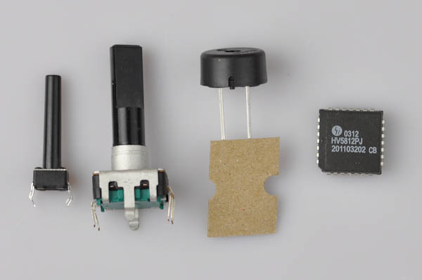
- 1x Piezo
- 1x Rotary encoder
- 1x Button
- 1x HV5812 driver
- 1x CR1220 Battery
Step 8a
First, place the piezo speaker. It goes in the footprint marked BUZZER, in the lower right.
The piezo is not polarized and can go in any way.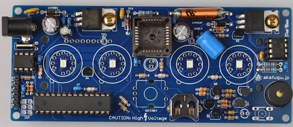
Step 8b
Place the button, just below and to the left of the piezo. It will click in place as you press it in.
Step 8c
Next is the rotary encoder. It will fit only one way. Make sure to press it all the way in.
Step 8d
Now insert the HV5812 chip in the socket. Look at the picture to match the orientation. Be careful not to insert it the wrong way as it is very difficult to remove from the socket once it has been placed.
Finally, insert the battery, + pointing up.
PART 9 - Another Test
Apply power again: You should hear a sequence of beeps as the clock boots.
Remove power.
PART 10 - Nixie Tubes
Next, we will insert the nixie tubes.
IN-2 Nixie tubes are very fragile, so be careful not to apply too much stress on them. If they crack, they will not function!
First locate the pin headers. Carefully insert one into each leg of the four nixie tubes. Push them in as far as they go, but do not force it.
Start with one of the nixie tubes:

Insert it into the leftmost footprint on the PCB. The legs may be uneven and need some straightening before they insert properly. Carefully nudge the uneven legs, and again make sure to be very careful not to crack the tube.

Once inserted, solder one of the legs on the back side. Be sure to check that the tube and pins sit parallell to the board before soldering the remaining legs.
Do not cut off the excess part of the legs on the pins behind, as that may damage them.
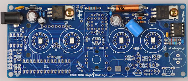
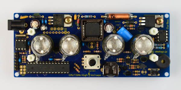
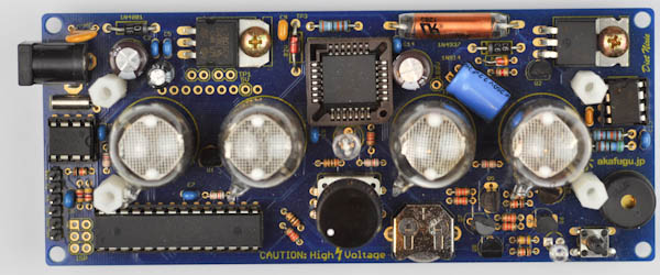
Repeat for all the other tubes. Here is how the board looks with all four tubes installed:
PART 11 - Live Check
Next, we will power up the board and check that all the tubes are functioning.
Apply power and wait until digits are shown in the tubes. Now press and hold the alarm button (lower right). After a few seconds you will hear a beep and the tubes will start to rotate between digits 0-9. Make sure every digit lights up. If not go back and check your soldering.
NOTE: The tubes will occasionally briefly show a blurry yellow "image" when applying power. This is normal and nothing to worry about.
PART 12 - Enclosure
Here are the components of the case:
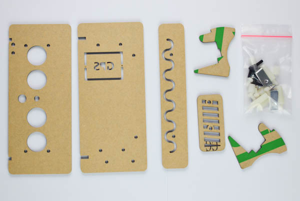
The protective film on the acrylic plates must be peeled off before assembly.
Step 12a
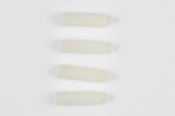
Open the bag that contains the screws, and extract the four long spacers. They are female to male and the short spacers (female-female)
The long spacers go into the front, and are fastened with the short spacers from the back.
Front view: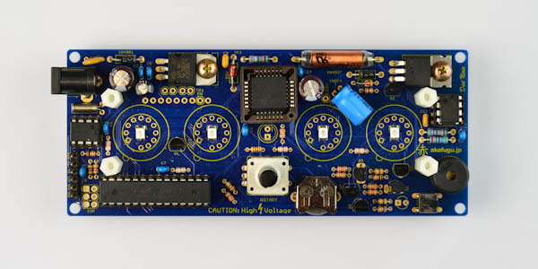
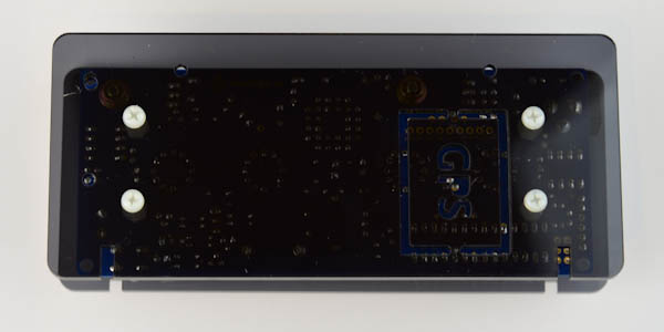
Back view: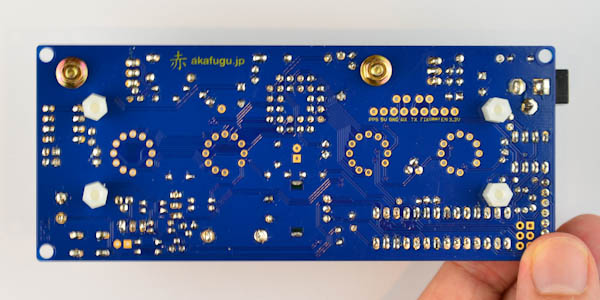
PS: The placement of the "nipple" on the IN-2 nixie tubes varies significantly between tubes. The bottom-left spacer will be quite close to the nipple of the leftmost tube. If it touches the spacer so that it will not stand straight, try and swap the placement of two nixie tubes (for a tube that has different nipple placement).
Again, be careful when handling the IN-2 tubes, as improper use of force may crack the glass envelope.
Step 12b
First, attach the four plastic nuts to the four long spacers:
Step 12c
Attach the volume knob on top of the rotary controller knob, and fasten it using a 1.5 allan bit -or- T-6 torx bit.
Step 12d
Next, place the top plate, and fasten it using the four black allan screws.
Step 12e
Place the back plate and fasten it using the four short plastic screws.
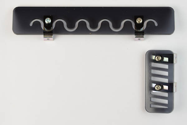
Step 12f
Next, we will prepare the two side plates. Note the orientation in the picture below.
You will need four short metal screws and four angled brackets. The long side of the brackets will mate with the side plates, and the short side will be used to attach to the main enclosure in the next step.
Step 12g
Next, we will use the four remaining short metal screws to attach the side plates to the top and right side of the enclosure.
Top side: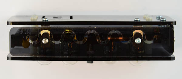
Right side: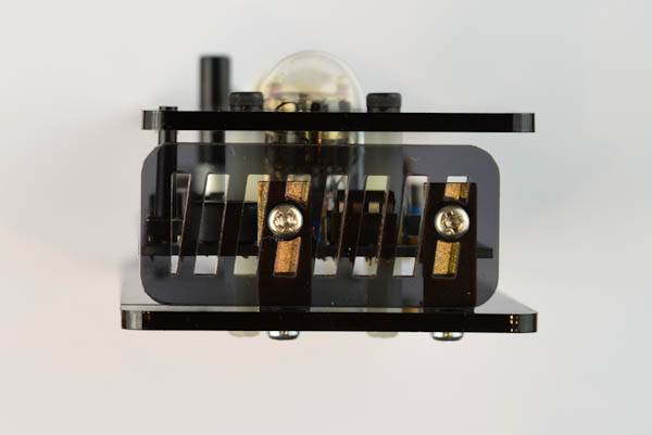
Step 12h
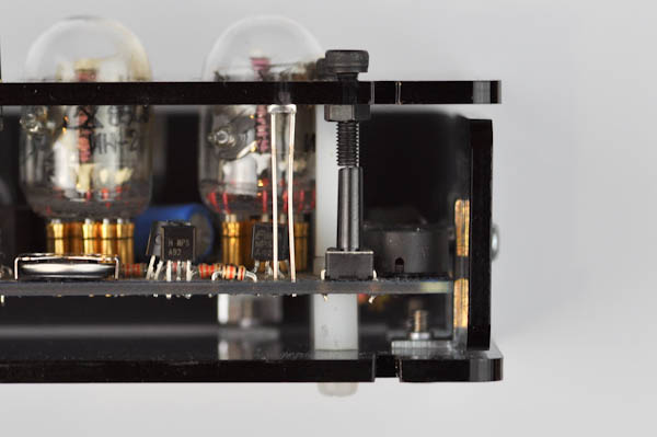
Find the long black screw and nut.
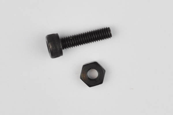
Push the screw through the hole in the lower right corner of the case, directly on top of the button. Screw in the nut underneath so that the screw sits directly on the top of the button. Check that pressing down on the screw presses the button down.
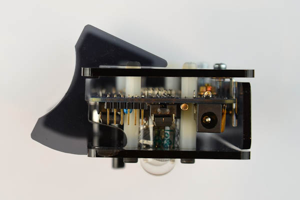
Step 12i
Next, we will fasten the legs. They will snap into place using the slots in the front plate.
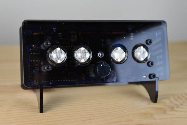
Finished: