Usage Instructions
You will need a USB mini-B cable. Plug the cable into your computer and attach the mini-B connector to the FTDI adapter. You should see the LEDs light up briefly.
The FTDI adapter requires drivers, that can be downloaded from theFTDI webpage.
The first time you connect the adapter, your computer will assign a serial port.
On OS X, the serial port will typically look like this: /dev/tty.usbserial-A700ft5E
On Linux, the serial port will typically look like this: /dev/tty.usbserial-A700ft5E
On Windows, the serial port will typically look like this: COM5
Usage as a Programming Adapter in the Arduino IDE
Once the adapter has been plugged in, open the Arduino IDE. Go to the Tools -> Serial Ports menu, and you should see the assigned serial port there. Make sure that it is selected.
Now, plug the 6-pin female header into your Arduino or Arduino compatible board. Make sure it goes the right way in: The names of the pins are marked on the adapter, and should be marked on your board as well.
Make sure you select the correct board type in the Tools -> Board menu. Once that is completed, you can use the upload button in the toolbar to upload your sketch.
Usage as a Debugging Port
Anything you print using the Serial library in Arduino will be printed to the serial port on your computer.
Now, anything you print using Serial.println will be sent through the FTDI adapter and to your computer. Click on the Serial Monitor button in the IDE to see the output. Make sure it is set to 9600 bps.
Switching between 5V and 3.3V (OLD version)
The FTDI adapter is configured to deliver 5V from the USB cable by default. It can also be configured for 3.3V. To do so, follow these instructions:
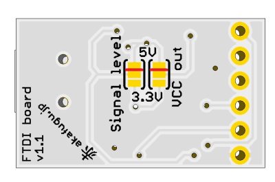
First, carefully cut the two traces shown with a cutter knife. Take care only to cut the actual trace and not to touch any of the are around. Pressing down firmly on the knife and moving it only slightly should do the trick.
To check that the trace is properly cut, you can check with a multimeter: Put the multimeter in continuity checking mode, and touch one probe to the top pad and one to the middle pad. It should not beep.
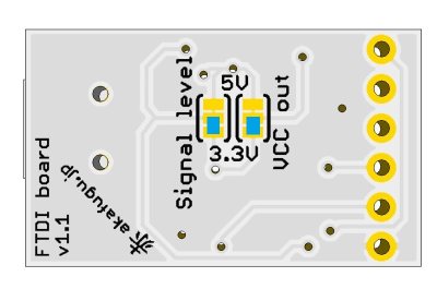
Next, put a solder bridge on each of the two areas shown, bridging the middle and bottom pads.
To verify that everything works, turn the board over, plug in a USB cable, set your multimeter to DC voltage measuring mode and touch the black probe to GND and the red probe to VCC. It should measure around 3.3V.
The 3.3V is supplied using an internal regulator in the FTDI chip. It can only supply 50mA maximum, so be careful not to use it for power-hungry applications.