There are two versions of the clock, each comes with a different set of components.
The newest VERSION 3 clock is listed first, with older versions following
VERSION 2 AND 3
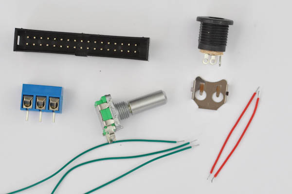
POWER BOARD
- 1x Power board PCB with SMD components pre-soldered
- 1x 2.1 mm panel mount Jack connector
- 2x short pre-stripped wires (VIN, GND)
- 3x long pre-stripped wires (5V, GND, HV)
CONTROL BOARD
- Control board PCB with SMD components pre-soldered
Resistors
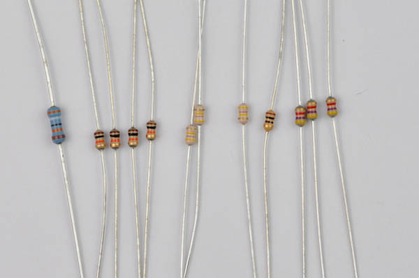
- 3x 4.7kΩ (Yellow, Violet, Red, Gold) (R2, R3, R4)
- 1x 10Ω (Brown, Black, Black, Gold) (R5)
- 4x 10kΩ (Brown, Black, Orange, Gold) (R1, R6, R8, R10)
- 4x 470kΩ (Yellow, Violet, Yellow, Gold) (R7, R9, R11)
- 1x 390kΩ (Orange, White, Yellow, Gold) (R12)
Capacitors
- 1x 10µF -or- 33µF (C1)
- 4x 0.1µF blue (C2, C3, C4, C5)
- 1x 0.1µF yellow (C6)
Other
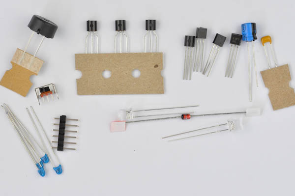
- 1x 82V zener diode
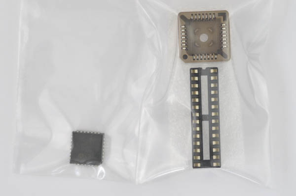
- 1x Atmega 328P microcontroller with Arduino bootloader and Firmware (IC1)
- 1x HV5812 display driver (IC2)
- 1x 28 pin socket (IC1)
- 1x PLCC-28 socket (IC2)
- 1x 2x17 shrouded header
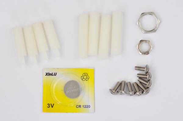
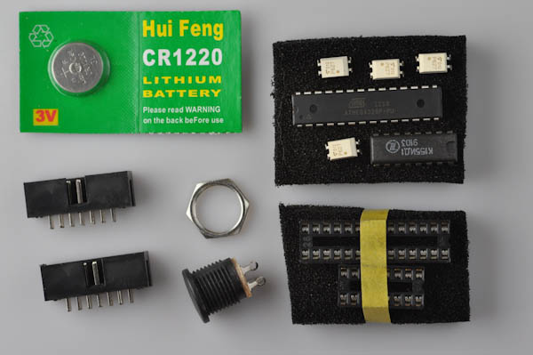
- 1x CR1220 battery
- 1x battery holder CR1220
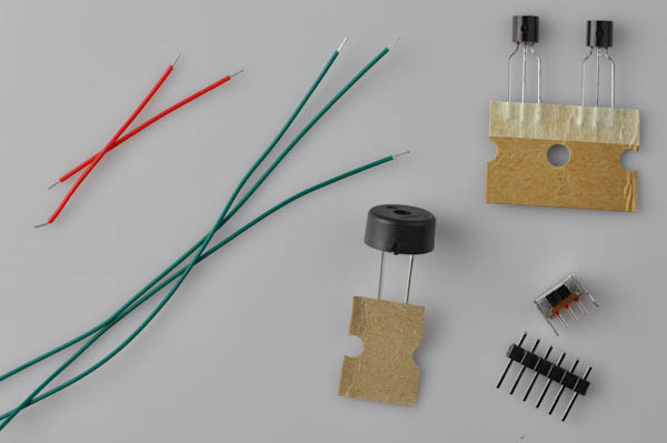
- 1x Piezo (BUZZER)
- 1x Rotary encoder (ROTARY)
- 1x 2N7000 Transistor (Q1)
- 3x MSPA42 high voltage transistors (Q2, Q4, Q6)
- 3x MSPA92 high voltage transistors (Q3, Q5, Q7)
- 4x TLP627 optocoupler (OPT1-OPT4) [http://www.toshiba.com/taec/components2/Datasheet_Sync/207/4346.pdf]
- 1x Slide switch
- 2x MPSA42 high voltage transistor (Q1, Q2)
- 1x 9V DC Adapter
DISPLAY BOARD
- 1x Display board PCB with SMD components pre-soldered
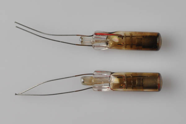
- 4x IN12 Nixie tubes
- 2x Orange 5mm LEDs
OTHER
- 1x 2x17 pin IDC cable
- 48x mounting pins (VERSION 3 only)
VERSION 1
POWER BOARD
- 1x Power board PCB with SMD components pre-soldered
- 1x 2.1 mm panel mount Jack connector
- 2x short pre-stripped wires (VIN, GND)
- 3x long pre-stripped wires (5V, GND, HV)
CONTROL BOARD
- Control board PCB with SMD components pre-soldered
Resistors
- 3x 4.7kΩ (Yellow, Violet, Red, Gold) (R2, R3, R4)
- 2x 10kΩ (Brown, Black, Orange, Gold) (R1, R6, R7)
- 1x 10Ω (Brown, Black, Black, Gold) (R5)
- 4x 330Ω (Orange, Orange, Brown, Gold) (R8, R9, R10, R11)
Capacitors
- 1x 10µF (C1)
- 3x 0.1µF (C2, C3, C4, C5)
Other
- 1x Atmega 328P microcontroller with Arduino bootloader and Firmware (IC1)
- 1x КМ155ИД1 (K155ID1) Nixie driver (IC2)
- 1x 28 pin socket (IC1)
- 1x 16 pin socket (IC2)
- 2x 2x7 shrouded header
- 1x CR1220 battery
- 1x battery holder CR1220
- 1x Piezo (BUZZER)
- 1x Rotary encoder (ROTARY)
- 4x TLP627 optocoupler (OPT1-OPT4) [http://www.toshiba.com/taec/components2/Datasheet_Sync/207/4346.pdf]
- 1x Slide switch
- 2x MPSA42 high voltage transistor (Q1, Q2)
- 1x 9V DC Adapter
DISPLAY BOARD
- 1x Display board PCB with SMD components pre-soldered
- 4x IN12 Nixie tubes
- 2x neon dot indicators INS-1
MISC
- 2x 2x7 pin IDC cables
CASE
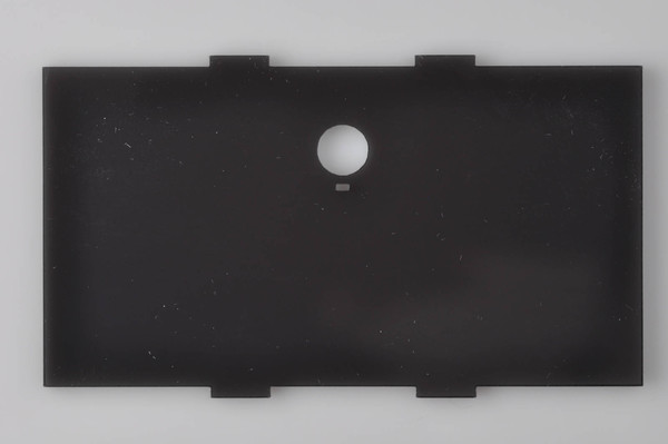
The case is the same in both versions of the clock.
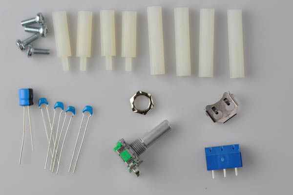
- 4x acrylic plates
- 4x metal screws
- 4x short nylon spacers
- 4x long nylon spacers