Usage Instructions
The shift register breakout board is easy to control with just about any microcontroller. You will need to hook up the VCC and GND pins to suitable VCC and GND pins on the microcontroller, and then hook up the three control lines (marked DIN, CLK and LATCH) to three I/O ports.
Arduino
To use the board with an Arduino or Arduino compatible board, you must connect wires to the five connectors at the top of the board:
- VCC -> to 5V connector on Arduino board
- GND -> to one of the GND connectors
- DIN -> to a digital pin (12 in the code example below)
- CLK -> to a digital pin (11 in the code example below)
- LATCH -> to a digital pin (10 in the code example below)
You can control just about anything that you can control directly with microcontroller outputs. Just remember that just as with microcontroller pins, the pins of the shift register cannot drive high-current outputs.
For this example: Let's try to attach LEDs. You will need 16 leds and 16 resistors. The easiest way to accomplish this is to use three breadboards interlocked horizontally like so:
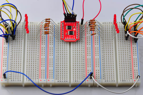
A rough schematic for this configuration is here:
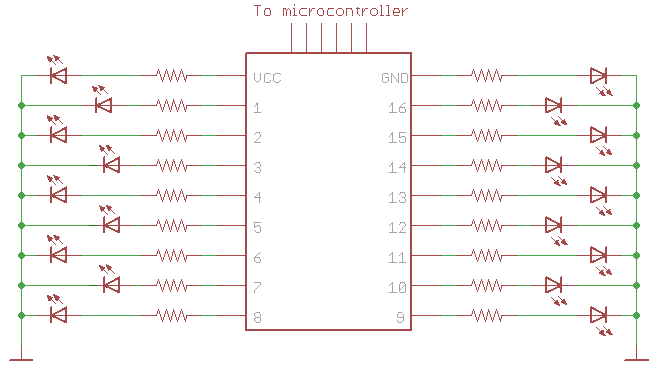
Resistor values between 240Ω and 1kΩ work fine for red LEDs.
Arduino Code
This assumes that DATA_HIGH/DATA_LOW/CLOCK_HIGH/CLOCK_LOW are macros that set the correct output pins on your controller.