Assembly Instructions
The TWIDisplay 14-segment LCD Display comes partially assembled: The main processor and auxilliary components are all soldered on, but the headers and actual display must be soldered on by the user.
Requirements
To assemble this kit, you will need:
- A soldering iron
- Solder
- A wire cutter (a diagonal type that allows you to cut the wires as close to the soldering points as possible is best)
- Helping hands or clips to hold the PCB in place when soldering (a vise will also work)
Optional:
- A multimeter
- Desoldering wick
- Solder sucker
- Protective glasses
See the equipment page for more details.
Step 1
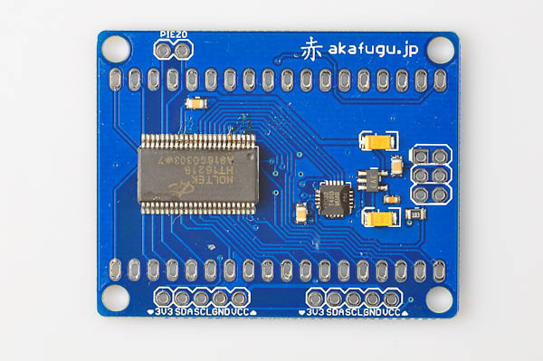
Top side:
Bottom side: (this is where the display and header(s) are inserted)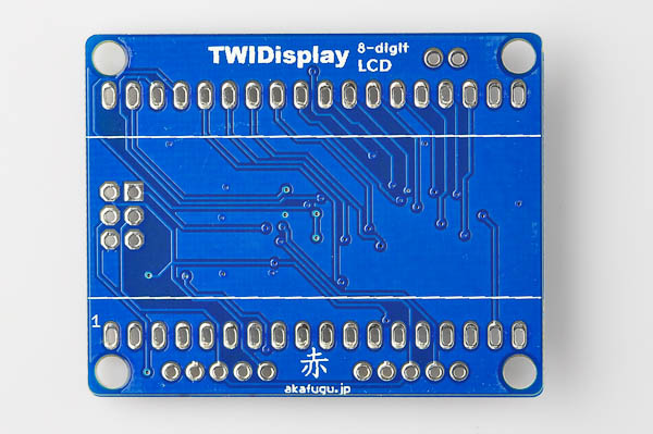
Two headers are included: One female and one male. You can use only one or both depending on your preference. If you add the second one, several displays can be daisy chained (using male-to female cables).
We'll show how to add the female header (repeat as neccesary to add the male header as well.)
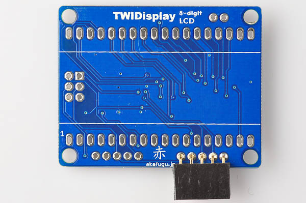
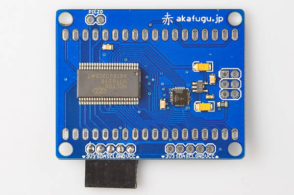
With the display turned on its back side, insert the header as shown.
Now turn the PCB over, and solder the header. The header may fall out when you turn the PCB over. You can use clips or a small piece of masking tape to hold the header in place. First solder one point, and then check orientation. If the orientation is bad, reapply heat and then carefully move the header. Once the orientation of the header is ok, you can solder the remaining points.
Step 2
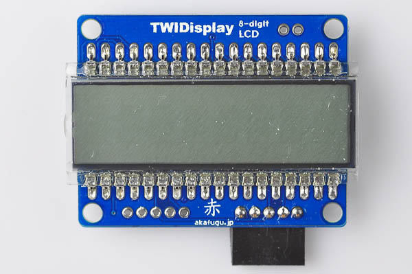
Now it is time to place the display. It should be inserted on the bottom side of the PCB. Orientation is important: On the left side, there is a mark in the display (a half-circle), this needs to go to the left side as shown (make sure the TWIDisplay text is aligned as shown in the picture)
<%= make_note( "If you ever want to reprogram the firmware of the display, you can do so using the 6-pin ISP header. You will need to solder 2x3 pin female header (not included). After soldering on the display, it will be difficult to add the ISP header, so you should add it immediately if required." ) %>
Carefully push all the pins through the PCB, and turn it over so that the pins point upward:
--missing picture--
Press the PCB down so that it sits flush against the display. Solder one pin on each side first, and check to see that the aligment of the display is good. Once you are happy with the alignment, solder the remaining pins.
Step 3
Finally, cut off the excess part of the display legs. Cut each leg close to the solder point.
When cutting the legs, they may come flying towards you at high speed, so be sure to wear protective glasses. It is also possible to hold the leg you are about to cut with pinchers to prevent it from flying.
Congratulations! The display is now fully assembled and ready for use.
Head on to the null for further instructions!