Header assembly - TWILCD Standard
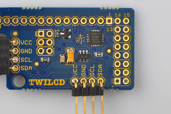
We will start by attaching the header pins that are connect to the Arduino (or other microcontroller) for use. On the board, you will notice that there are two rows of four pins marked with VCC,GND,SCL,SDA. One is for connecting to the microcontroller, and the other one allows you to daisy-chain extra displays (or any other of Akafugu's TWI/I2C compatible products).
Let us do one header at a time: Insert it from the top of the board, pointing outward, as shown in the picture below. It may fall out when you turn the board over to solder: Attaching it with clips or a small piece of masking tape is a good idea.
Now turn the board over to solder: Solder one pin first, then check that the alignment and angle is ok. If not, reapply heat and gently nudge the connector until it sits properly. Once orientation is ok, solder the remaining pins.
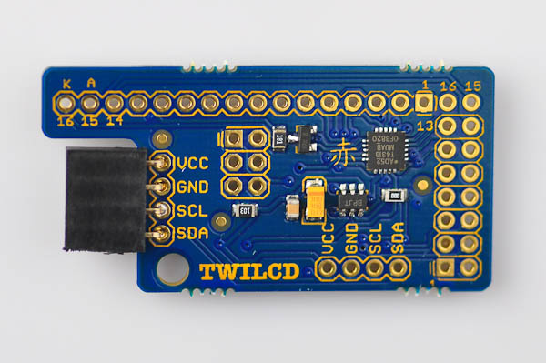
Turn the board over again, and insert the other header, then solder it the same way. We put the female header on the top left header, but you can do it the other way around too.
PS: If you do not plan to use the daisy-chaining feature, you can attach only one header row. Please note that it is difficult to add another header row later on after you have soldered on the display, so be sure to solder both header rows if you want to be able to daisy-chain the displays.
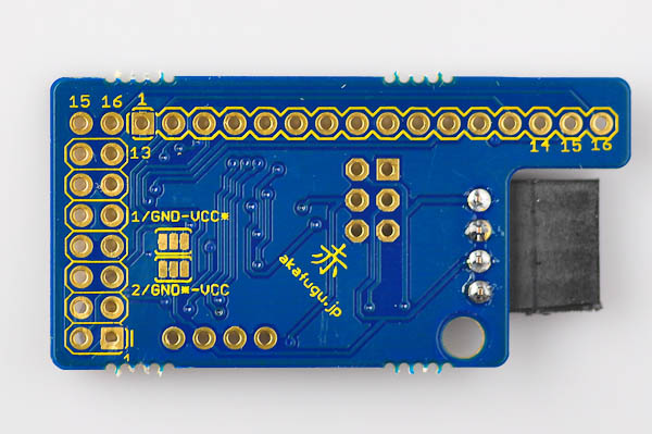
Here is how the back side will look after soldering:
Next, turn the board back over and solder place the male connector.