IV-17/IV-4 6-digit Shield - Parts List
The IV-17/IV-4 6-digit shield comes with the following parts:
- 1x IV-17/IV-4 PCB with half-cut holes for easy tube assembly
- 6x IV-17 -or- IV-4 alphanumeric display tubes
- 6x 51Ω resistors
- 2x 750Ω resistors
- 2x 4300Ω resistors
- 2x 47000Ω resistors
- 2x 10000Ω resistors
- 1x 2x9 pin male header
- 1x 2x10 pin male header
Note: IV-17 and IV-4 tubes look identical except for the marking on the back and can be used interchangably. Unless your kit is otherwise marked, we ship with IV-4 tubes.
IV-17-IV-4 6-digit Shield Assembly
Step 1a
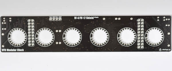
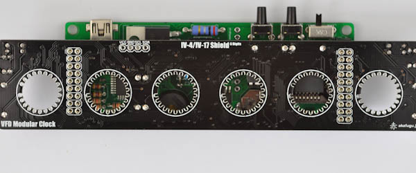
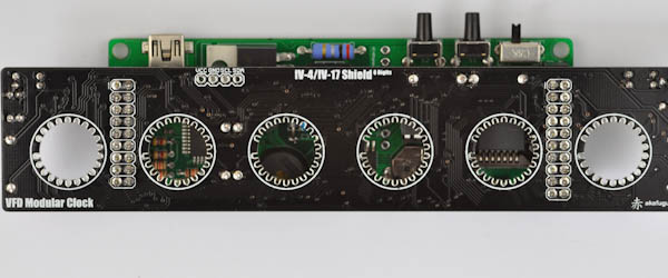
First take some time to familiarize yourself with the PCB. The pins of each of the six IV-17/IV-4 VFD tubes slide through the six holes in the PCB.
Here is the PCB:
Step 1b
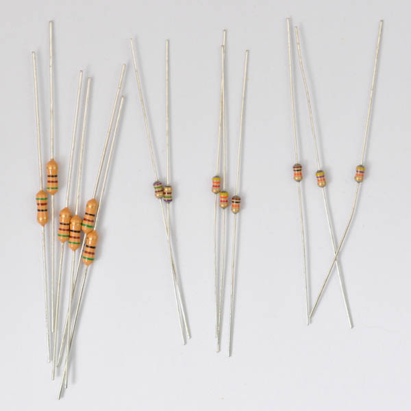
Let us start by soldering the resistors. There are 5 different types:
- 6x 51Ω 1/4W resistors
- 2x 750Ω 1/6W resistors
- 2x 4300Ω 1/6W resistors
- 2x 47000Ω 1/6W resistors
- 2x 10000Ω 1/6W resistors
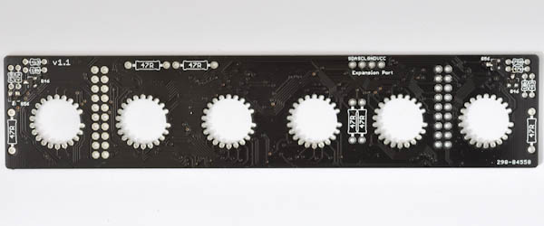
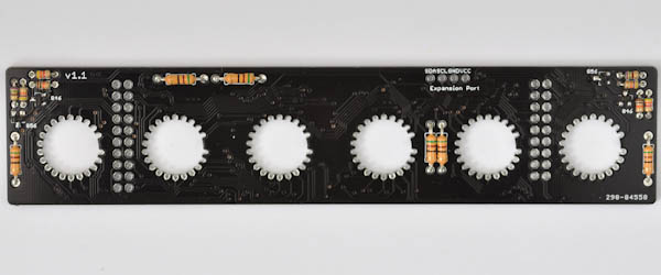
Start with the 6 large 1/4W 51Ω. Bend the legs and insert one resistor into each pair of holes marked 51R (some revisions have 47R printed instead of 51R).
The resistors insert from the bottom of the board (so that the actual resistor fits over the text. Bend each of the legs outward and turn the board over to solder all the legs. Once that is done, clip off the excess parts of the legs.
The final resistors go to the left and right part of the board. Each hole is marked with the required value: 750R for 750Ω, 4k3 for 4300Ω, 4k7 for 47000Ω and 10k for 10000Ω.
If you are unsure of the values, measure the resistors with a multimeter first.
Step 1c
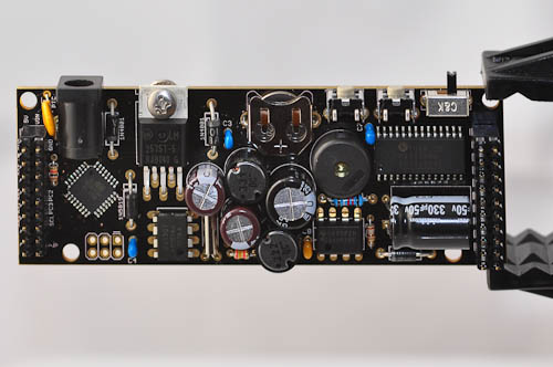
Now, it is time to solder the pin headers on either side. The easiest way to do this is to find the base board and insert the 2x9 pin header into the left side of the board (long pins facing down), and the 2x10 pin header into the right side (again, long pins facing down).
Once that is done, carefully place the IV-17/IV-4 6-digit board so that the holes on the sides of the board match up to the pins. The board should rest flat against the pins. Solder one pin first, check alignment, then one on the opposide side. Repeat until you have soldered one pin in each of the four corners of the board. Finally, solder all the remaining pins together.
Step 1d
The tubes are next: Let us start with the leftmost tube.
Each tube has one pin that is shorter than all the others. It is folded to the side against the bottom of the tube. This is an unconnected pin. If it sticks out, fold it agains the bottom of the tube.
The footprint on the PCB where each leg of the tube is to be soldered on has a single gap that corresponds to the unconnected pin on the tube.
To prepare the tube for insertion, gently press all the legs of the tube together like so:
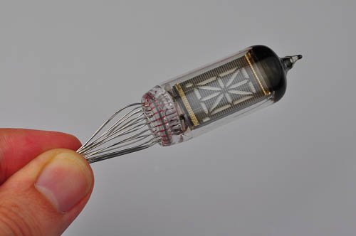
This will make it easier to insert the tube in the hole.
Step 1e
Some of the pictures that follow show the 4-digit PCB rather than the 6-digit one. The steps are otherwise identical.
The tube should be inserted from the top of the board (the side that says VFD Modular Clock and IV-17/IV-4 6-digit Shield)
Rotate the tube so that it's orientation matches the gap. Gently press all the legs of the tube together so that it slides easily through the hole. Press it slowly downward.
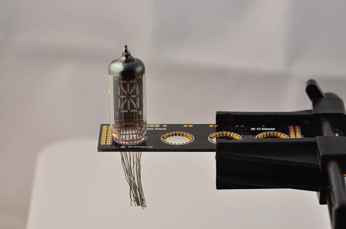
Step 1f
Now turn the board upside down and using either your fingers or tweezers pull each leg outward so that it touches against the hole where it is to be soldered.
It is possible to push the tube so that it rests against the PCB. This is the recommended configuration if you do not plan to build an enclosure for the clock. If you do plan to build it into an enclose, you may need to leave some gap. How much gap to leave and how to properly align the tubes will be different in each case depending on your enclosure.
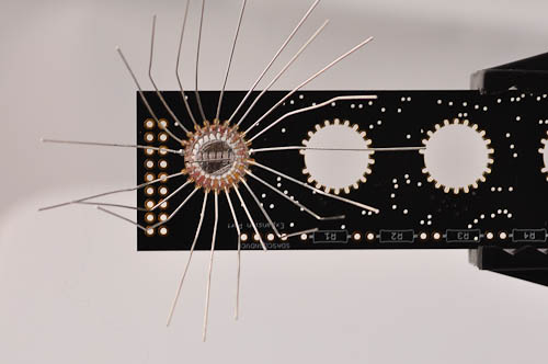
Step 1g
Make sure all the legs are pulled properly in place, bend them outward to help hold the tube steady. It is best to use pinchers here to make sure you get good contact. When you are happy with the alignement, solder one of the pins. When you remove the solder iron tip the solder will stay molten for a short period, so be sure to hold tube steady for a little while after you remove the solder iron tip.
Now check alignment. If you are not happy, re-apply heat and carefully move the tube until you are happy.
Now solder a pin on the opposite side of the one you just soldered. Again check alignment until you are happy.
Using a vise is by far the easiest way, but if you don't have one, piling up books on either side of the board to prop it up while soldering is a good substitute.
Next, solder all the remaining pins.
Step 1h
Now it is time to clip of all the excess parts of the pins. Clip off each one with a flat clipper. Before clipping off each leg, make sure that there is solder on the leg and that it is attached securely to the board.
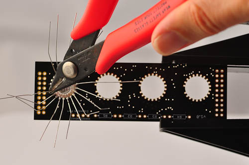
The final result will look something like this:
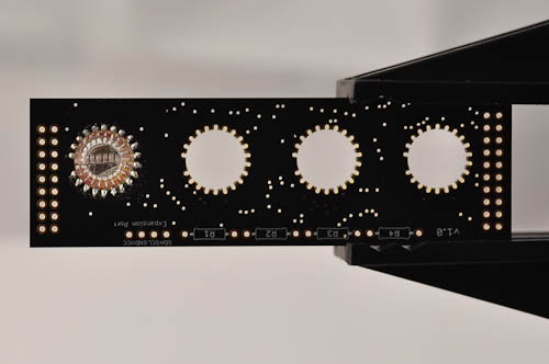
Step 1i
Repeat the above procedure for the remaining 5 tubes.
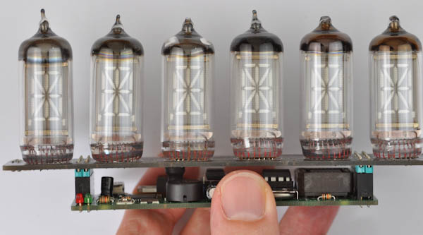
Congratulations, you have now finished assembling the IV-17/IV-4 6-digit display shield.
Now Head over to theusage page for instructions on how to set the time.