VFD Base Board Assembly Instructions - Version 2.3 (mk2)
Follow these instructions to assemble the base board of the VFD Modular Clock.
There are many components to solder, so take your time.
PS: These instructions are for version 2.3 of the base board.
Preparations
Make sure you have sufficient space on your work area. Remove the parts from their packaging. Some of the parts look very similar, so be careful to follow the instructions properly so that the correct part ends up in the correct place.
Some of the components are polarized (such as the electrolytic capacitors), so make sure that you pay attention to polarization when this is mentioned.
We will solder the parts in an order that allows us to test that we are on the right track during the soldering work: We'll start by testing that the board works properly by soldering in the piezo, then we'll assemble the parts the generate the high voltage power supply for the VFD tubes, and finally the remaining components (real time clock, eeprom and misc other parts).
Step 1: Initial board check
The board runs off USB power: It must be powered either from a computer's USB port or through a 5V USB power adapter (not included). It uses an USB mini-b connector.
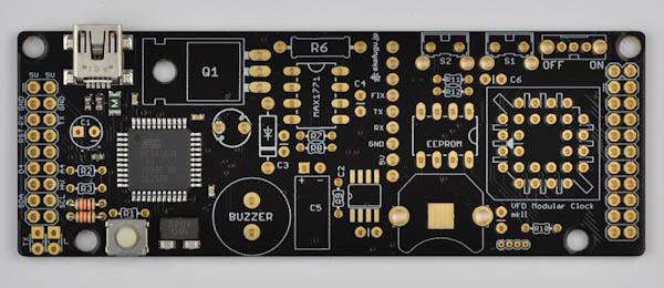
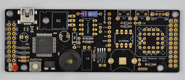
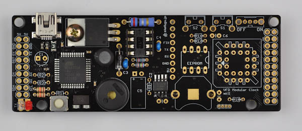
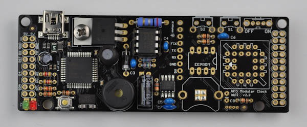
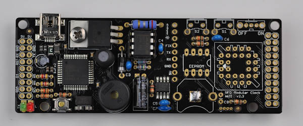
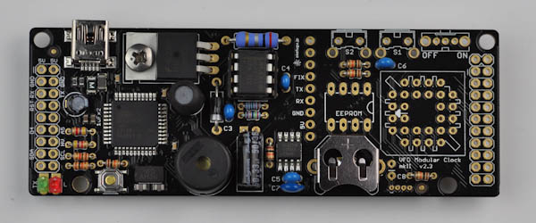
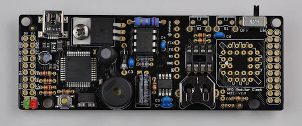
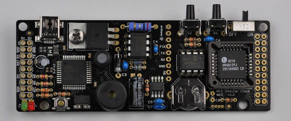
TOP VIEW:

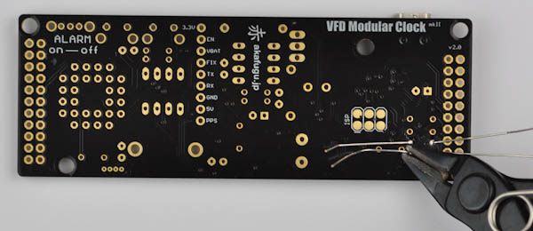
BOTTOM VIEW:

Step 1a:
Before we power to board to test that it is running properly, we will solder in a few components to make it easier to check.
We will start with the following components:
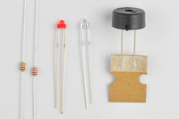
- 2x 1kΩ (Brown, Black, Red, Gold) resistors (R4, R5)
- 2x 1.8mm LEDs (colors vary) (TX, L)
- 1x Piezo buzzer (BUZZER)
Step 1b - Resistors
We will start with two 1kΩ (Brown, Black, Red, Gold) resistors. You may insert and solder one at a time, or both at once.
Resistors are color coded, but the color code can be hard to read, especially in dim light. If in doubt, use a multimeter set to resistance mode to measure the resistance of each resistor before soldering.
To insert, bend each leg 90 degrees, and insert into the holes of the footprints marked R4 and R5 on the PCB board.
Resistors are not polarized and can go in any way.Push all the way in so that the resistors lie flat against the board, then bend the legs outward so that the resistors don't fall out when you turn the board over to solder.
Turn the board over and solder. Using a flat wire clipper, cut off the remainder of each leg.
PS: See this video if you are unsure about how to measure the resistance of a resistor.
Step 1b - 1.8mm LEDs
Next, we solder the two 1.8mm LEDs, they go to the bottom left of the board. The leftmost footprint, marked TX is for the transmit LED, it will blink when you upload new code to the board. The right one, marked L, will pulse when you reset the board.
There are two different LED colors included, but it doesn't matter which goes to TX and which goes to L.
LEDs are polarized and must go in the correct way: The long leg goes into the square pad (top) and the short leg into the circlular pad (bottom).
Once inserted, they are soldered in the same way as the LEDs: Bend each leg, turn the board over to solder, then clip off the remainder of the legs.

Step 1c - Piezo
Now find the piezo: It is the large black disk with a hole in the middle. Remove the tape from the piece of cardboard attached.
It goes into the part marked BUZZER on the board, in the top right area. Orientation is not important. Bend the legs outward to hold it in place while soldering.
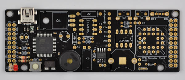
Step 1d - Test
We have now soldered enough components to test that the microcontroller functions correctly. You will need an USB mini-b cable for this step.
Insert the USB mini-b cable into the USB port of the base board, and attach the cable to your computer. It is also possible to use a 5V USB power adapter (such as a cellphone charger) to power the board.
You should hear a beep after a few seconds.
If you press and hold the reset buttons for a short while, then reset it, it should be possible to see the LED marked L pulse. After it stops pulsing, the board will beep again.
DO NOT CONTINUE UNLESS YOU HEAR A BEEP.
Step 1e - Driver Installation
In order to use the board together with the Arduino IDE, it is neccesary to set up drivers. If you do not intend to reprogram the board, you may skip this step.
The VFD Modular Clock mk2 is set up to work as an Arduino Leonardo board, and shares the same driver as our null board.
To set up the driver, follow the installation guide for Akafuino L:
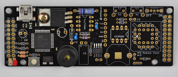
Step 2: Boost Converter
Before starting this step, be sure to remove the USB cable from the board.
Now it is time to build the boost converter. The boost converter takes the 5V from the USB cable and converts it to 40 volts, required to light up the VFD tubes.
For this step, we will solder the following components:
- 0.2R resistor (red, black, silver, gold) -or- 0.27R (R6)
- 10kΩ resistor (brown, black, black, red, brown) (R7)
- 240kΩ resistor (red, yellow, black, orange, brown) (R8)
- 1x 10µF Electrolytic Capacitor (C1)
- 1x 33µF Electrolytic Capacitor (C2)
- 1x 22µH Inductor
- 1x UF4004 Diode
- 1x FQP50NL06L mosfet
- 1x 8-pin IC socket
- 1x MAX1771 8-pin DIP chip

The appearance of the inductor differs, but it will look like either one of the items pictured here:

Step 2a - Resistors
First we will place the three resistors used for the boost converter:
- 0.2R 1W resistor (red, black, silver, gold) (R6)
- 10kΩ resistor (brown, black, black, red, brown) (R7)
- 240kΩ resistor (red, yellow, black, orange, brown) (R8)
The 0.2 ohm resistor is bigger than the other resistors.
Step 2b - Ceramic Capacitors
Find two of the 0.1µF blue/yellow ceramic capacitors. They go to C3 and C4.
Ceramic Capacitors are not polarized and can go in any way.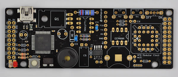
Step 2c - UF4004 Diode
Find the UF4004 diode, it goes to the left of C3. Diodes are polarized and must be inserted the correct way. The white band on the diode should line up with the white line on the PCB footprint.

Step 2d - FQP50NL06L mosfet
Locate the large (TO-220) mosfet, along with the metal screw and nut.
The mosfet goes to Q1. The legs should be bent 90 degrees before inserting it into the footprint. Fasten the screw and nut before soldering.
Step 2e - 8-pin IC socket
Next, we solder one of the 2 8-pin IC sockets.
IC Sockets are marked with a half-circle indentation in one end. Insert so that this matches up with the half-circle in the silkscreen on the PCB.Solder only one leg first, then check that the orientation of the component is correct. If not, re-apply heat and adjust as neccesary. Once you are happy with the orientation, solder the remaining legs.The component may fall out when you turn the board over to solder. You may use a small piece of masking tape or similar to hold it in place.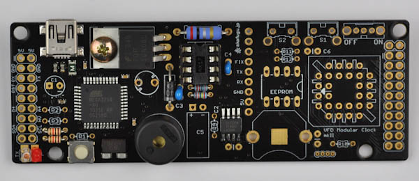
Step 2f - Inductor
Next up is the 22µH inductor.
It goes in the footprint right underneath the MOSFET (and to the right of the microcontroller). It is not polarized, so orientation doesn't matter.
Step 2g - Electrolytic Capacitors
There are two electrolytic capacitors included:
- 1x 10µF Electrolytic Capacitor - blue or black (C1)
- 1x 33µF Electrolytic Capacitor - black (C2)
The capacitance value is printed on the capacitor if you are in doubt.
The 10µF capcitor goes in C1 to the left.
Electrolytic Capacitors are polarized and must be inserted the correct way. The long leg goes in the square hole. The short leg goes in the round hole (marked with a minus sign)The 33µF capacitor goes in C2 in the middle bottom. Before inserting, bend the legs 90 degrees, and again make sure the orientation is correct and that the long leg goes into the square hole.

Step 2h - MAX1771
There are two 8-pin IC chips included. Each has the name of the chip written on top. Find the MAX1771 and place it into the IC socket we placed previously.
The half-circle indentation on the socket should match the half-circle indentation in the chip. If the chip has no indentation, it will have a small dot instead that should point upward.
The IC chip must be fitted in the correct way. The half-circle (or dot) on top of the chip should match the half-circle marking on the silk screen / socket.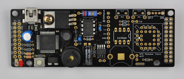
Step 3: Testing the boost converter
Insert the USB cable once more. As before, the L LED will pulse for a few seconds, and then you will hear a beep.
Now, find your miltimeter and set it to DC voltage mode.
We will measure voltages on the header on the left side of the board. Place the black ground probe on one of the two pins marked GND.
First, place the red probe on one of the two pins marked 5V. The voltage should read around 5V, but usually slightly lower.
Now, move the red probe to the pin marked HV. Now the voltage should read around 42V. For this value, anything in the range 35V to 50V is ok.
DO NOT PROCEED TO THE NEXT STEP UNLESS YOU ARE ABLE TO VERIFY BOTH 5V AND 42V VOLTAGES.
Step 4: Misc Components
Before starting step 4, make sure that the clock is not connected to power. It is dangerous to solder the board while power is connected.
We will now place various components. Start by locating the remaining resistors.
Step 4a: Remaining resistors
Locate the remaining resistors:
- 2x 4.7kΩ (Yellow, Violet, Red, Gold) resistors (R2, R3)
- 5x 10kΩ (Brown, Black, Orange, Gold) resistor (R1, R9, R10, R11, R12)
R2 and R3:

R1, R9, R10, R11 and R12:

**Step 4b: Remaining ceramic capacitors.
Locate the remaining ceramic capacitors:
- 2x 0.1µF blue/yellow ceramic capacitor (C5, C6)
- 1x 10µF ceramic capacitor (C7) - dark blue with short legs
These are not polarized and can go any way.
PS: Kits shipped from mid-February 2014 include two additional ceramic capacitors. These are wider and colored in a darker blue than the 0.1µF capacitors.
Step 4c: Battery holder
First, melt some solder against the center pad of the battery holder footprint:
PS: The center pad may already have some solder on it, in which case you can skip this part.
Now place the battery holder: Orient it as shown in the outline on the board. To prevent it from falling out while soldering place clips or some masking tape over it.
Solder only one leg first, and check orientation. If you are not happy, re-apply heat and adjust. Be very careful: Since the entire area of the battery holder is metal it conducts heat very quickly, so allow it to cool down before touching it.
Once both legs are soldered properly, wait a little bit again for it to cool down.
Step 4d: 8-pin socket
Next, we solder one the remaining 8-pin IC socket.
IC Sockets are marked with a half-circle indentation in one end. Insert so that this matches up with the half-circle in the silkscreen on the PCB.Solder only one leg first, then check that the orientation of the component is correct. If not, re-apply heat and adjust as neccesary. Once you are happy with the orientation, solder the remaining legs.The component may fall out when you turn the board over to solder. You may use a small piece of masking tape or similar to hold it in place.
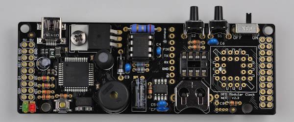
Step 4e: Alarm switch
Place the slide switch in the top right, nob pointing upward. Use clips or some masking tape to hold it in place while soldering.
Slide the switch to the left after soldering it.
Step 4f: Tactile switches (buttons)
Place the two buttons S1 and S2, the button part should point upward. Push them all the way in so that they stay in place while soldering.
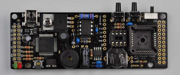
Step 4g: PLCC socket
Find the PLCC-28 socket. Insert it so that the shape matches that of the PCB footprint.
Solder only one leg first, then check that the orientation of the component is correct. If not, re-apply heat and adjust as neccesary. Once you are happy with the orientation, solder the remaining legs.The component may fall out when you turn the board over to solder. You may use a small piece of masking tape or similar to hold it in place.
Step 4h: Battery
Now it is time to place the battery. The part of the battery marked + should face upward (there is a + printed on the battery holder to remind you of this). Slide it all the way in. The battery will keep the real time clock running even when the clock has no power.
Step 4i: Insert HV5812 and EEPROM
First, find the remaining 8-pin chip. This is the EEPROM. It goes to the remaining open 8-pin socket.
The half-circle indentation on the socket should match the half-circle indentation in the chip. If the chip has no indentation, it will have a small dot instead that should point upward.
Next, find the HV5812. Once placed, this chip cannot be removed without a specialized tool, so be very careful that the orientation is correct.
The side with the slanted indentation (and dot) must point to the left. Put the chip on top of the header and apply even pressure and push it all the way down.
Step 4j: Female headers
Now only the two female headers remain. Place them so that they point upward: The 2x9 one goes on the left side, the 2x10 one on the right side. They are symmetrical, so direction doesn't matter.
Use clips or masking tape to hold them in place while soldering. As always, solder one leg first and adjust alignment if neccesary.

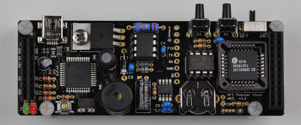
Step 4k: spacers & screws
There are now only four plastic screws and four plastic spacers remaining. These are used in the four mounting holes around the base board to stabilize it.
Be careful when you screw in the screws, as they are quite fragile and break easily.
The top-right screw is a tight fit against the female header, so be extra careful when inserting it.
**Step 4l: 1µF and 10µF ceramic capacitors
These two parts are only included in kits shipped after mid-February 2014. If your kit does not include these two capacitors, read below for details.
Turn the board over. The two capacitors are marked as follows:
CONGRATULATIONS: You have assembled the VFD Modular Clock Base Board.