VFD Modular Clock Assembly Instructions
The VFD Modular Clock is not particularily difficult to assemble, but it does have a fair amount of parts, so patience is required. We recommend the VFD Modular Clock for people who already know the basics of through the hole soldering.
Important: The VFD Modular Clock generates high voltage (25-40V). This is enough to give you a small shock if you are not careful. If you are not comfortable with working with high voltage, do not assemble the clock!
Required Equipment
Have a look at the Equipment List for details!
You will need at a minimum the following:
- A solder iron or solder station
- Solder (0.6 or 0.8mm solder is a good choice)
- A multimeter
- Wire clippers
- Pinchers
- Helping hands -or- vise
- Clips to hold parts in place while you solder them (masking tape can be used as an alternative)
Tutorials
If you need to brush up your soldering skill, have a look at the following:
Assembly Instructions
The instructions are separated into two parts, the base board and the shield. The base board is where the majority of parts go. The display shield contains the actual display tubes and plugs in over the base board.
Base board
There are two versions of the base board, versions 1 and 2. Version 2 has "VFD Modular Clock mkii" printed on the backside of the PCB board. Version 2.3 has VFD Modular Clock mkii v2.3 printed on the top right on the front side of the PCB board.
- Base board version 2.3 (mk2) Assembly Instructions
- Base board version 2 (mk2) Assembly Instructions
- Base board version 1 Assembly Instructions
Shield
There are five different shields available, choose the one you have:
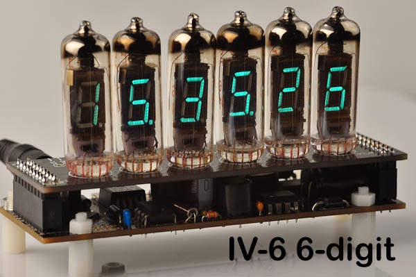
- IV-6 Display Shield Assembly Instructions
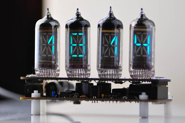
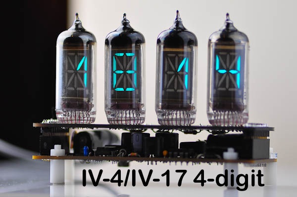
- IV-17/IV-4 4-digit Display Shield Assembly Instructions
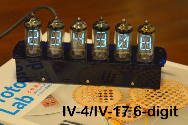
- IV-17/IV-4 6-digit Display Shield Assembly Instructions
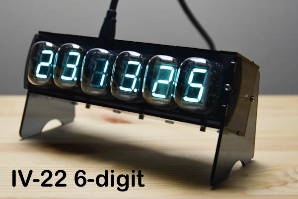
- IV-22 Display Shield Assembly Instructions
- IV-18 Display Shield Assembly Instructions
- IV-11/6 6-digit Display Shield Assembly Instructions


Enclosure
- IV-4/IV-17/IV-6 Acrylic Case Assembly Instructions
- IV-4/IV-17 6-digit Acrylic Case Assembly Instructions
- IV-22 Acrylic Case Assembly Instructions
- IV-18 Acrylic Case Assembly Instructions
- IV-11/6 6-digit Acrylic Case Assembly Instructions
Troubleshooting
If you should manage to destroy or misplace any of the components during assembly we can provide spares. Contact us by email.
For general questions about assembly and troubleshooting, use ourVFD clock forum.