Nixie IN12 Display Board Assembly Instructions (VERSION 3)
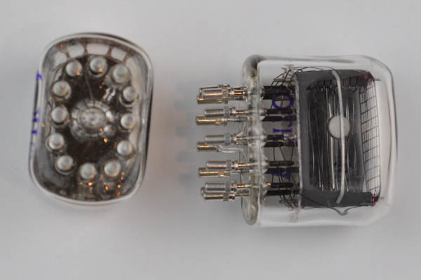
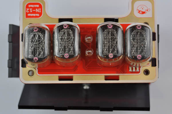
The IN12 Display Board contains the actual Nixie tubes as well as two LEDs for the colon indicator.
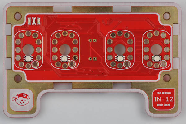
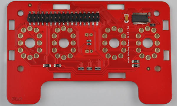
The board comes with some surface mount parts already soldered on: Male headers that serve as the connection point to the logic board, four RGB backlight LEDs and three indicator LEDs. Finally, a PWM LED driver used to conrol the LEDs.
The Nixie tubes, socket pins and colon indicator LEDs must be soldered on before use.
Top view
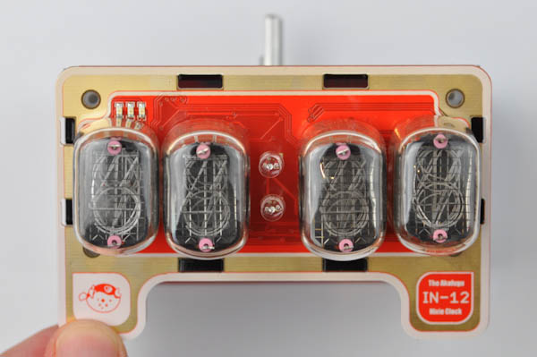
Bottom view
Step 1 - Testing the RGB LEDs
Before we solder on the Nixie tubes, let us test the RGB LEDs.
Connect the flat cable from the logic board to the display board. Orientation is important: Make sure the protruding box on the cable connector matches the print on the silk screen.
Attach the power jack again and power up the board. You should hear a melody as before. All the LEDs will light up briefly (don't look directly at them, as they will be very bright when not covered by the nixie tubes).
After the clock has finished booting, the lights will turn off. Try the following:
Rotate the rotary encoder knob: You will see the RGB leds light up in different colors.
Flip the alarm switch up: When the alarm is on the rightmost orange LED will light up.
Remove the power adapter from the wall, wait at least 30 seconds, then unplug the power jack. Finally, gently unplug the flat cable.
Step 2 - Nixie tubes
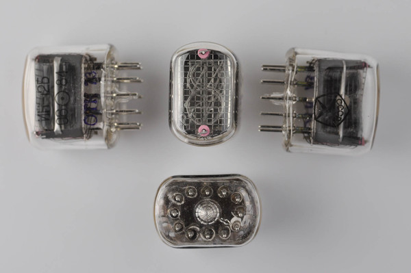
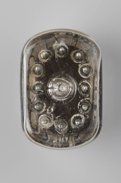

The orientation of the Nixie tubes are important. Look underneath a tube: You will see an arrow next to one of the pins. This pin should match up to the hole with a white circle around it on the PCB.
The tubes are based on old technology and production methods, and have various imperfections: Each tube will have a slightly different width and tilt.
Before inserting the tubes, insert all the included socket pins, 12 for each tube. Insert and gently push all the way in.
The easiest way to make sure all the tubes line up nicely on the board is to insert all four and then gently turn the board over to lie on its back. Doing it this way ensures that the front of the clock will look nice and even.
Make sure to insert the tubes so that the socket pins push all the way in.
Also, since the RGB LEDs are towards the bottom of each tube, the PCB will tend incline slightly when the board is put on its back. Gently nudge the board and tubes to lie close to perpendicularily against the PCB.
Gently solder one pin on each tube, reheat and adjust orientation as neccesary. When you are happy, solder one more pin on each tube (on the opposite side of the one you just soldered). Reheat again and adjust as neccesary.
Once the tube orientation looks good, add solder to all the remaining pins.
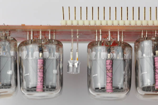
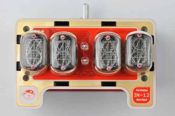
Step 3 - Colon indicators
Next, let us solder the two colon indicator LEDs. They go to the two footprints in the middle of the board. As usual, make sure that the long leg of the LED goes into the square hole.
For the best result, do not push the LED all the way in, but leave about a centimeter between the head of the LED and the board. Make sure both LEDs are mounted at the same distance from the board.
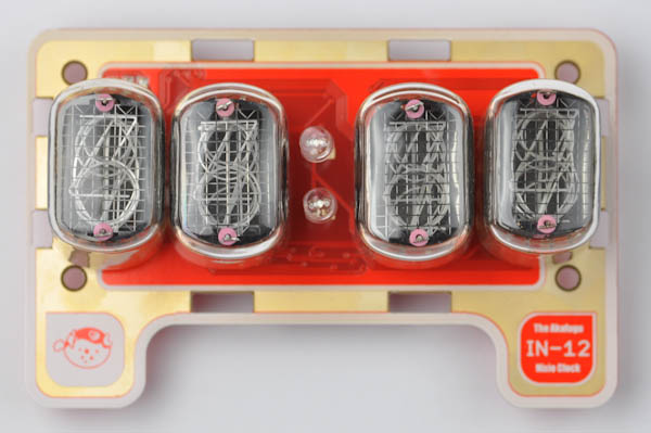
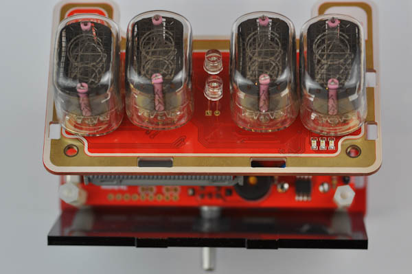
Here is how the board looks after the LEDs are assembled
Step 4 - Case assembly
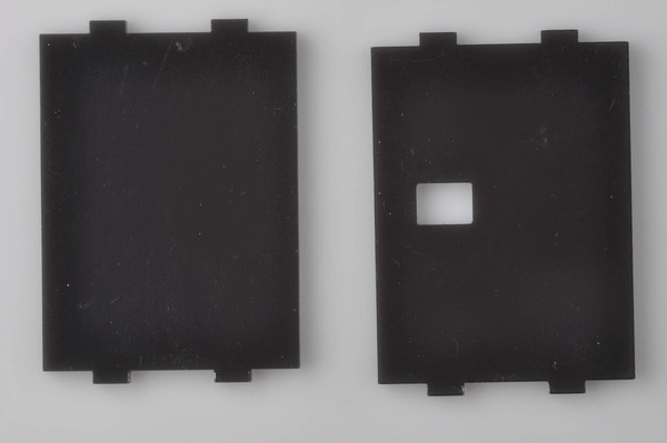
Locate the four acrylic plates. Each one is unique and will only fit in one place. The top plate has a hole for the rotary encoder knob, the right plate has a hole for the alarm switch.
First, carefully remove the protective layer on each side of the plates.
TOP BOARD
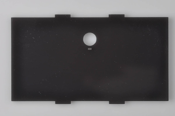
BOTTOM BOARD

LEFT AND RIGHT BOARDS
Step 4a - Top plate
Tip the power/control board on its side so that the rotary encoder points up. Slightly unscrew the two top screws on the back.
Insert the top plate: It is very important that it aligns so that both the hole for the rotary encoder shaft and the tiny square hole for the protruding tip on the rotary encoder base lines up (otherwise the board will bulge outward).
Screw the two screws back in, making sure everything fits snugly.
Step 4b - Remaining plates
Tip the power/control board back up.
Insert the remaining three plates. Take care so that orientation is correct.
Step 4c - Attaching display board
Attach the display board cables again, as described in step 1).
Press the board against the case, making sure each plate is properly align. Press gently until all mounting holes snap into place.
Screw in the remaining four screws: Be very careful with the two bottom ones as they will have to be screwed in a slight angle since the holes are very close to the display tubes.
Step 4d - The final touch
Locate the small nut:

Screw it in on top of the rotary encoder shaft:
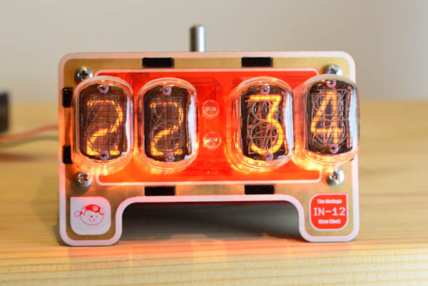
CONGRATULATIONS! You have now finished assembling The Akafugu Nixie Clock. Proceed to the Usage page for instructions on setting time and alarm.
PS: When disassembling the clock, the top spacers will unscrew together with the top screws. If you have trouble inserting the top screws properly it is possible to first attach the top screws to the long spacers, then screw the top plate back on.