Step 1
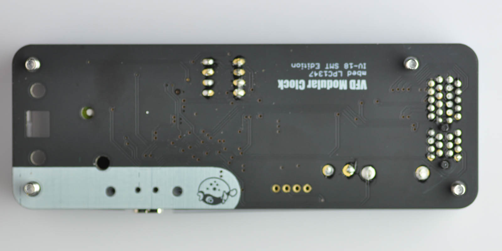
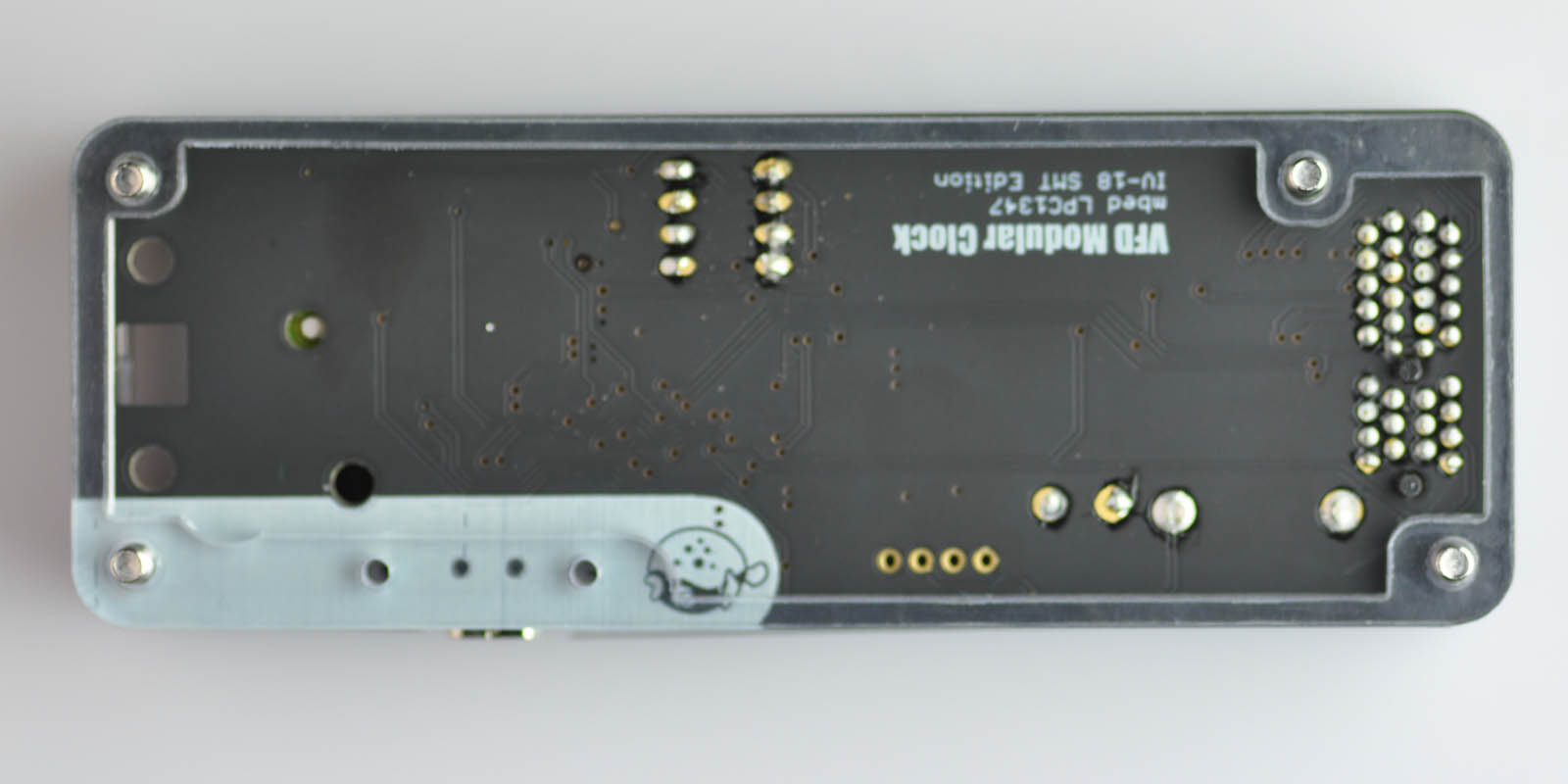
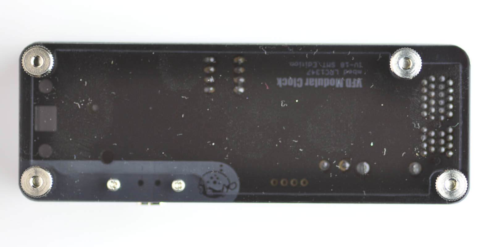
Inspect the PCB board.
Basic version: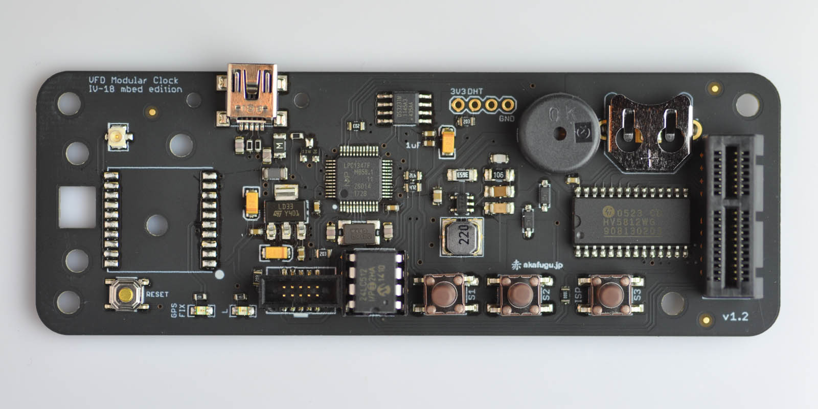
GPS version: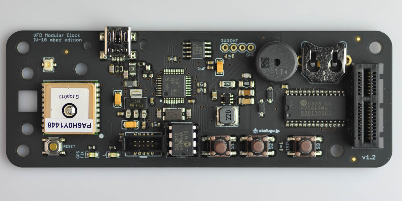
There are two LEDs on the board, in the lower left corner.
The LED marked L will blink when the clock is started up.
The LED marked "GPS FIX" will blink until a GPS sattelite fix is aquired. Once it stops blinking, the clock will set itself according to sattelite time. Aquiring a GPS fix typically takes 1-2 minutes. If it takes more than 5 minutes, the clock may be unable to get a sattelite fix. Try moving it closer to a window. On the basic version, the GPS FIX LED has no function.
Step 2
Test that the clock is functioning.
- Insert the IV-18 tube
- Insert USB cable
- Turn on power
- Insert CR1220 backup battery
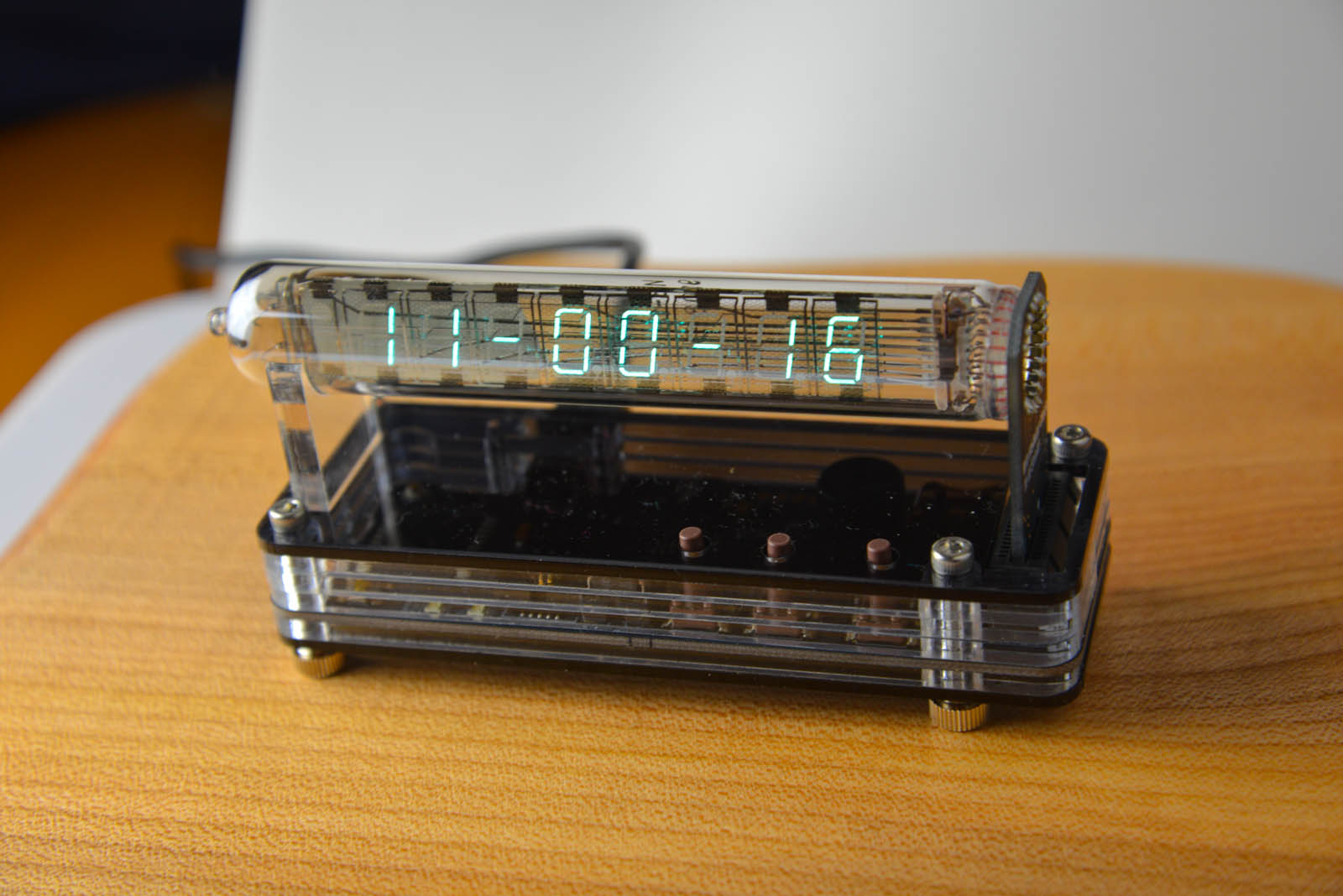
The clock should now start up. Verify that you can see the time displayed.
Disconnect the clock before continuing.
Step 2
We will now assemble the enclosure.
Step 2a
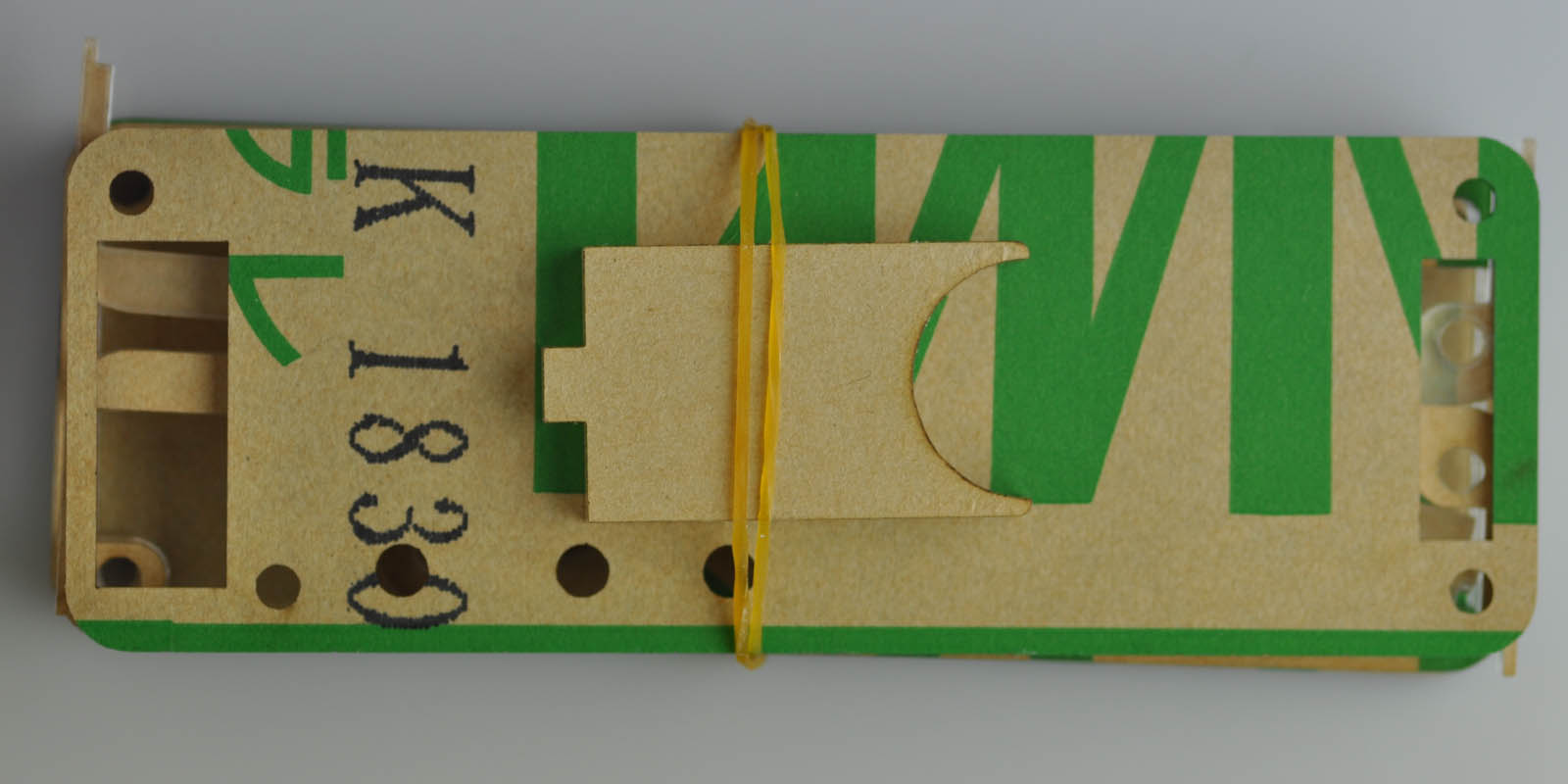
- Remove paper (or plastic) cover from all enclosure parts.
Note that there are two parts that look very similar, but are actually different: Pay attention to the upper left area, one of the pieces has a rounded corner, and one has a straight corner.
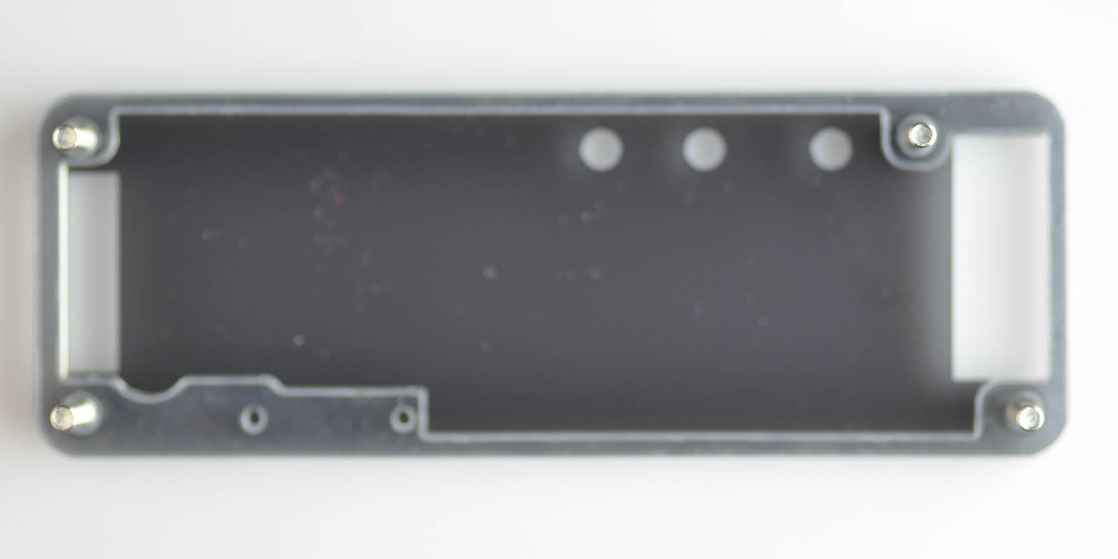
Rounded corner: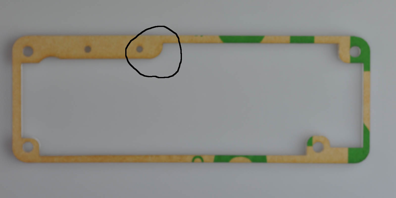
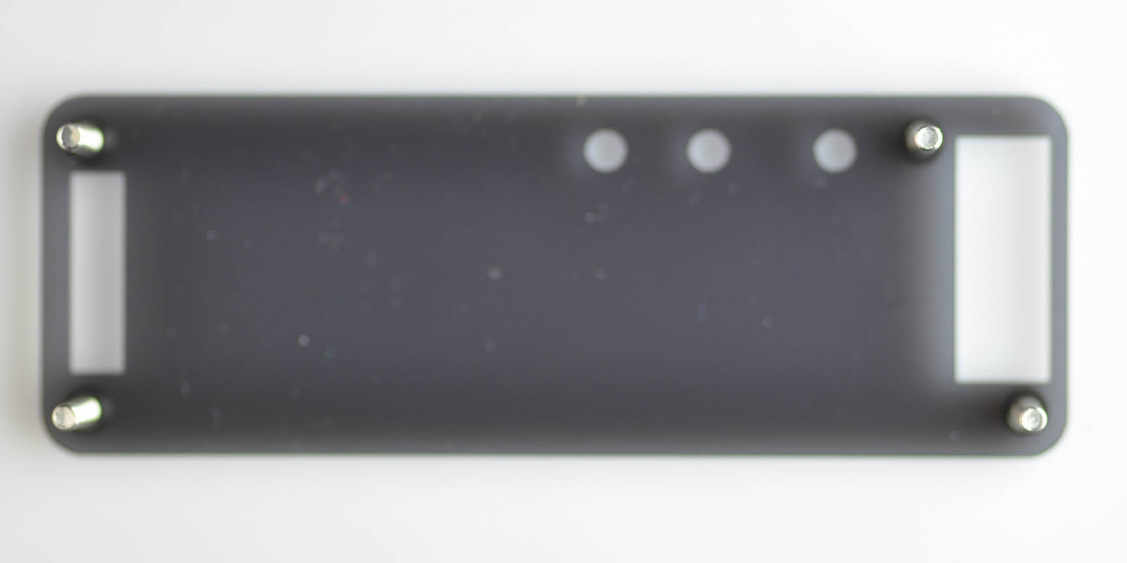
Straight corner: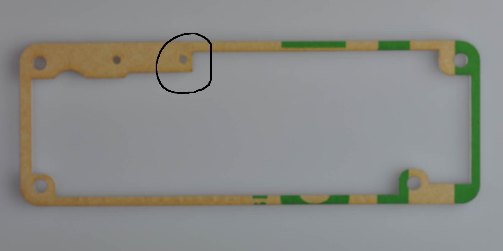
During assembly, we will use the piece with the straight edge first, and then the rounded one.
Step 2b
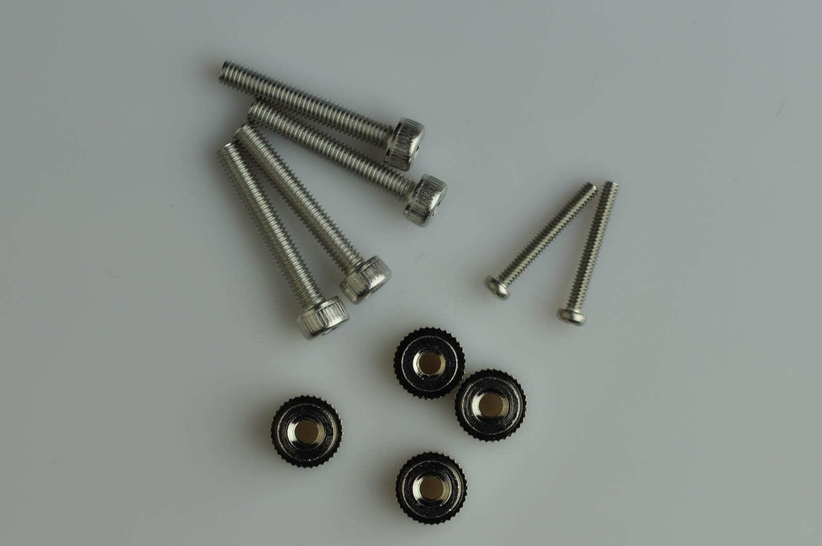
Place the four screws upside down:
Step 2c
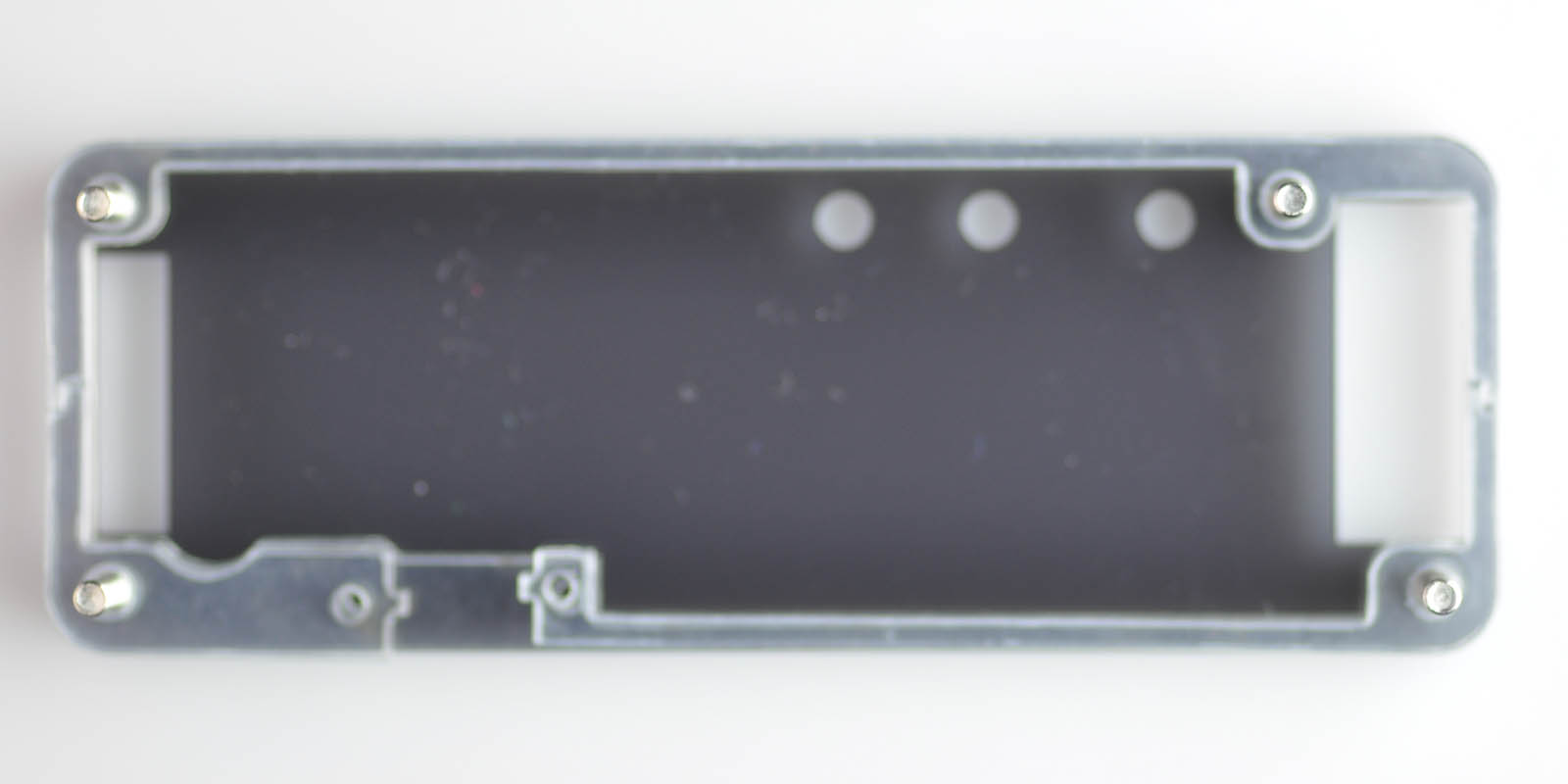
Place the top gray piece
Step 2d
Place the transparent straight edge piece
Step 2e
There are three separate small transparent pieces. There are two sets of these, for a total of six pieces. The two sets of three pieces are identical.
Place the first layer as shown below
Then the second layer
Step 2f
Place the PCB board.
Step 2g
Place the transparent rounded edge piece.
Step 2h
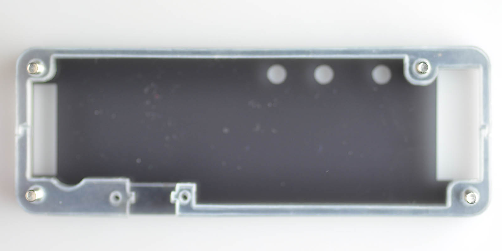
Place the gray bottom piece
Step 2d
Insert the two small screws, and fasten them.
Step 2e
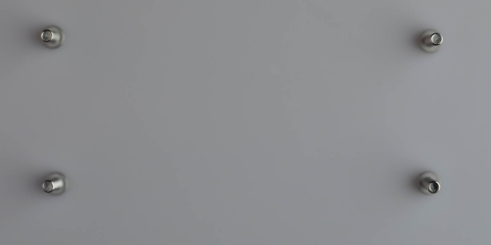
Screw the four feet into the four screws along the edges.
Step 2f
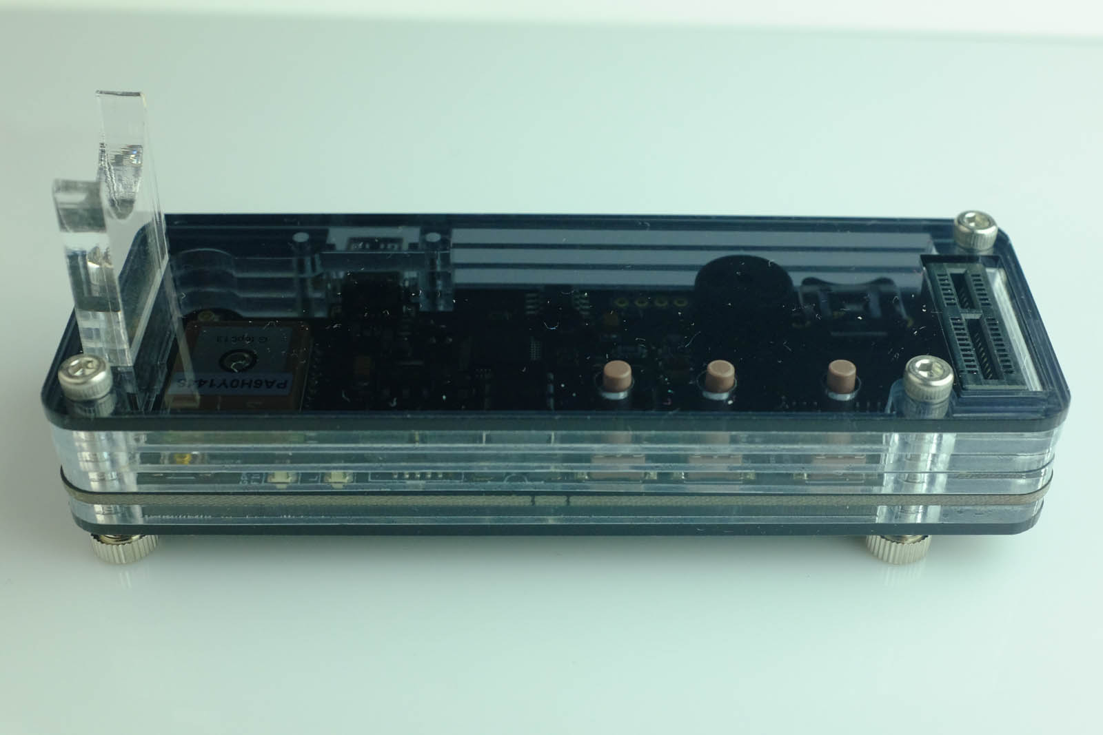
Turn the clock around and place it on its feet.
Insert the thick 5mm tube support on the left side.
Step 2g
Insert the display tube board again.
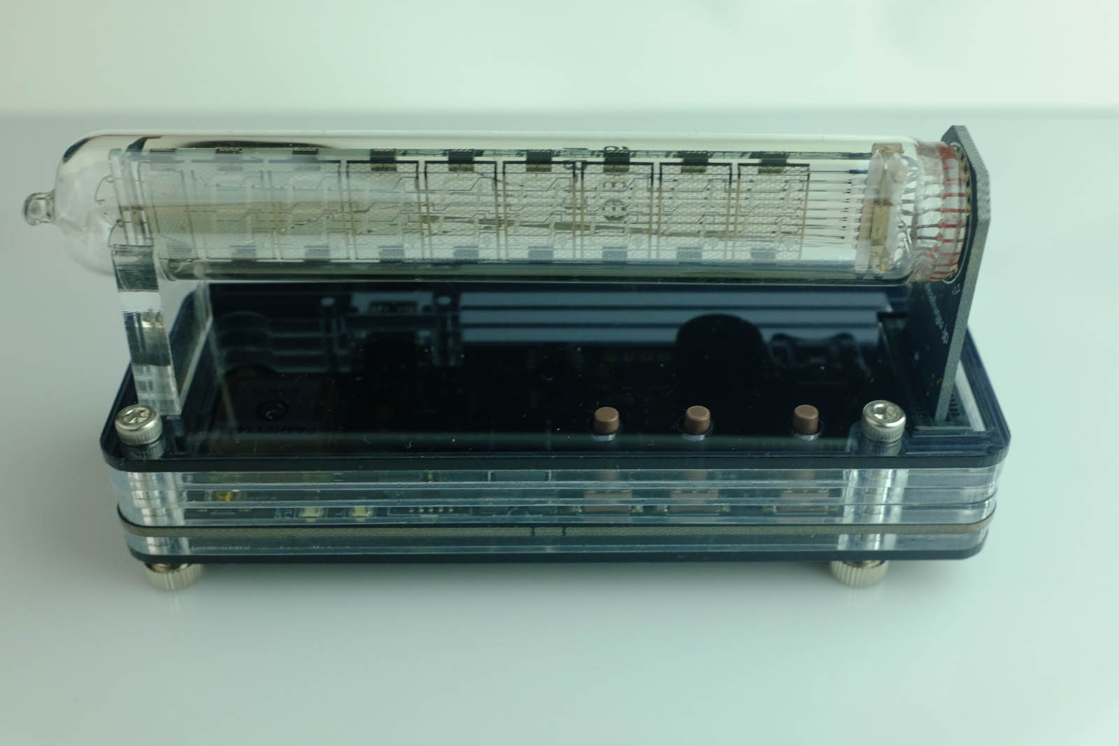
Step 2h
Finished!