Nixie Control Board Assembly Instructions (VERSION 3)
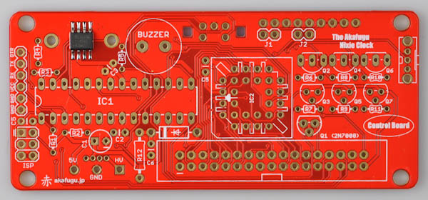
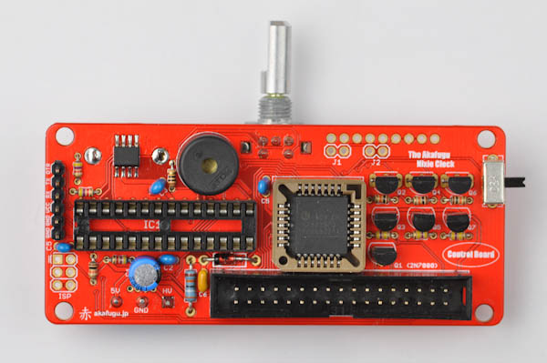
The Nixie Control Board contains the microcontroller and real time clock as well as the drive circuitry for the Nixie tubes (a HV5812 chip and high voltage transistors).
With the exception of the Real Time Clock chip, which comes pre-assembled all the other parts are Through The Hole (PTH) parts that must be soldered on.
The soldering process is not particularily difficult, but there are many parts so take your time and go slowly.
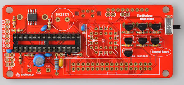
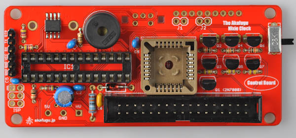
Front view
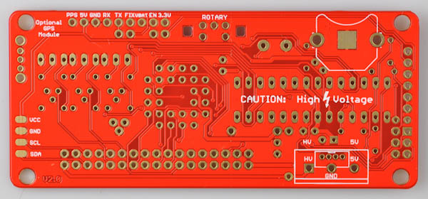
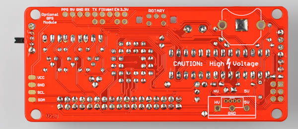
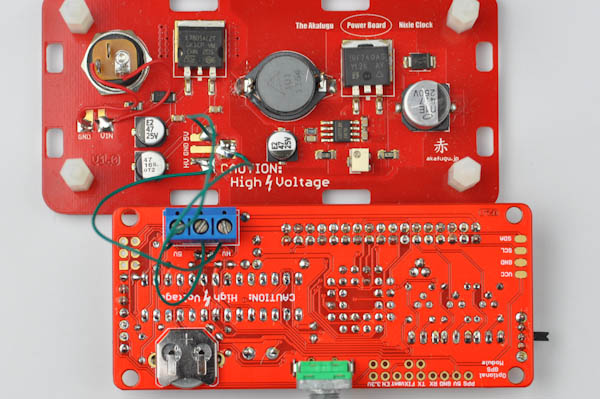
Back view
Step 1
Take some time to familiarize yourself with the board and all its components. We will start with the low profile components (resistors) first and then move on to the higher profile ones. This makes the board easier to handle along the way.
Take special note of the resistors. There are several different values, and the board will not work correctly unless they are installed in their designated places.
Each resistor is color coded as follows:
- 3x 4.7kΩ (Yellow, Violet, Red, Gold) (R2, R3, R4)
- 1x 10Ω (Brown, Black, Black, Gold) (R5)
- 4x 10kΩ (Brown, Black, Orange, Gold) (R1, R6, R8, R10)
- 3x 470kΩ (Yellow, Violet, Yellow, Gold) (R7, R9, R11)
- 1x 390kΩ (Orange, White, Yellow, Gold) (R12)
(Note that R12 is bigger than the other resistors)
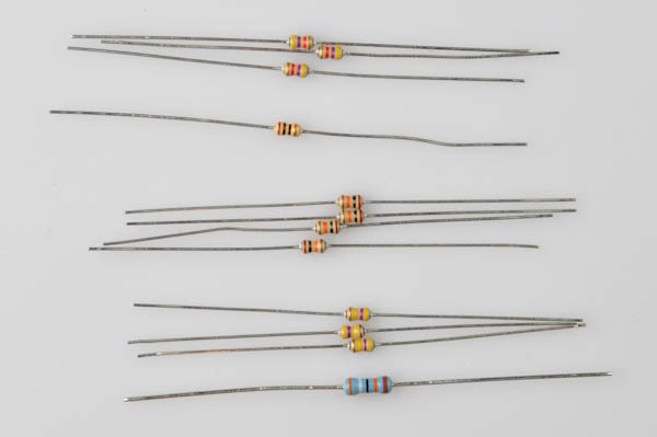
It can sometimes be diffuclt to correctly identify the correct colors, especially in dim light. If in doubt, use your multimeter to check the resistance (set the multimeter in resistance mode and touch one probe to each end of the resistor).
Step 2 - First resistor
Let us start by inserting one of the four included 10kΩ (Brown, Black, Orange, Gold) resistors into R1.
Resistors are not polarized and can go in any way.Pull the resistor's legs so that it ends up flat against the PCB board, bend the legs outward so they don't fall out when you turn the board over.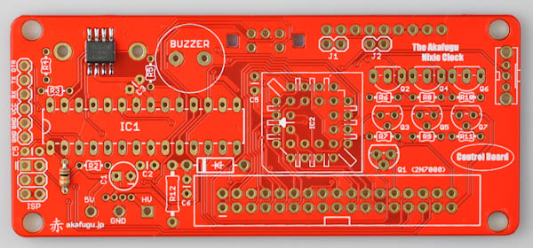 Solder each of the two legs, and carefully clip off the excess part of each leg:
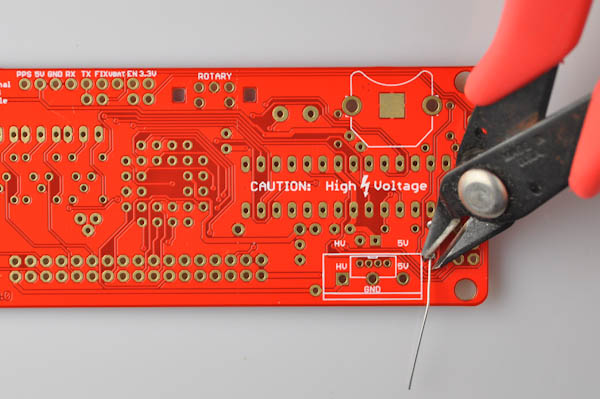 Step 3 - Other resistors ====== The remaining resistors are soldered in the same way. R6, R8 and R10: 10kΩ (Brown, Black, Orange, Gold)
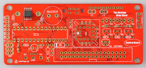 R2, R3 and R4: 4.7kΩ (Yellow, Violet, Red, Gold)
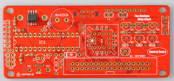 R5: 10Ω (Brown, Black, Black, Gold)
 R7, R9 and R11: 470kΩ (Yellow, Violet, Yellow, Gold)
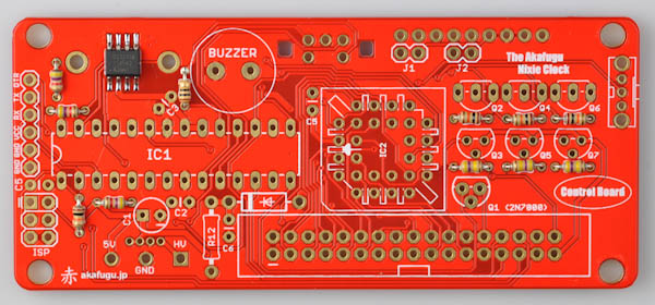 R12: 390kΩ (Orange, White, Yellow, Gold)
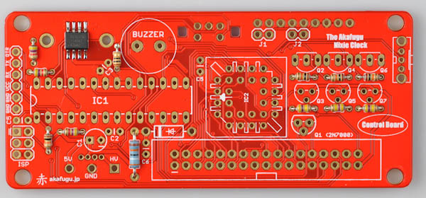 Clip off the excess parts of the legs after soldering.
Step 4 - 0.1µF Ceramic Capacitors
Next locate the blue 0.1µF ceramic capacitors. They go into C2, C3, C4 and C5, and are soldered in the same way as the resistors.
Ceramic Capacitors are not polarized and can go in any way.Clip off the excess parts of the legs after soldering.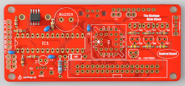
Step 5 - 82V power supply
Next, let us insert the two components that together with the R12 resistor make up the 82V power supply: The yellow 0.1µF ceramic capacitor and the 82V zener diode (the only diode included with the kit: A black cylindrical component with a white stripe on one end.)
The zener diode goes above and to the right of R12: Make sure the oriention is correct: The white stripe on the diode should line up with the white stripe on the PCB footprint.
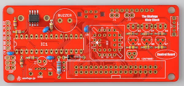
The 0.1uF capacitor goes into C7.
Ceramic Capacitors are not polarized and can go in any way.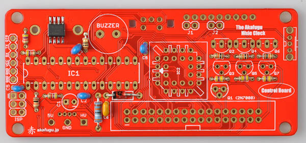
Step 6 - 28-pin IC Socket
There are two IC sockets included, one 28-pin DIP and one square 28-pin PLCC socket.
Solder the 28-pin DIP socket first.
IC Sockets are marked with a half-circle indentation in one end. Insert so that this matches up with the half-circle in the silkscreen on the PCB.The component may fall out when you turn the board over to solder. You may use a small piece of masking tape or similar to hold it in place.Solder only one leg first, then check that the orientation of the component is correct. If not, re-apply heat and adjust as neccesary. Once you are happy with the orientation, solder the remaining legs.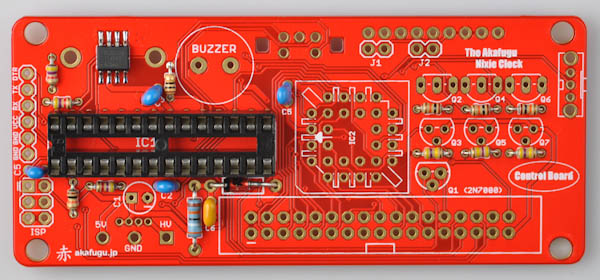
Step 7 - 10µF/33µF Electrolytic Capacitor
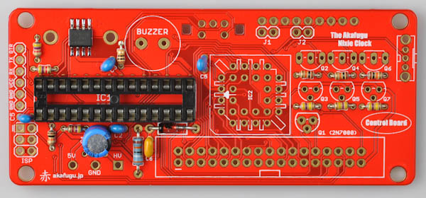
Next up is the 10µF (or 33µF) electrolytic capacitor. The one pictured is blue, but some kits are supplied with a black one. It will have 10µF (or 33µF) sprinted on the side. It goes into C1 in the lower left side of the board.
Electrolytic Capacitors are polarized and must be inserted the correct way. The long leg goes in the square hole. The short leg goes in the round hole (marked with a minus sign)Bend the legs outward before turning the board over to solder.Clip off the excess parts of the legs after soldering.Step 8 - Slide switch
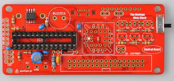
Next up is the slide switch. It goes on the far right hand side of the board. Insert it so that the slider points out as shown in the picture.
The component may fall out when you turn the board over to solder. You may use a small piece of masking tape or similar to hold it in place.Solder only one leg first, then check that the orientation of the component is correct. If not, re-apply heat and adjust as neccesary. Once you are happy with the orientation, solder the remaining legs.This component will become very hot when soldering, so be careful when touching it.Step 9 - Transistors
There are 7 transistors included in all. They all have their identification number printed on them, so make sure not to mix them up.
The MPSA42 transistors have wide legs, while the MPSA92 and 2N7000 transistors have narrowly spaced legs.
Transistors are polarized and must be inserted the correct way. The half-circle shape of the transistor should match up with the half-circle on the silk screen.- Q1: 2N7000 (bend the middle leg to insert into the footprint)
- Q2, Q4 and Q6: MPSA42
- Q3, Q5 and Q7: MPSA92 (bend the middle leg to insert into the footprint)
Step 10 - Piezo
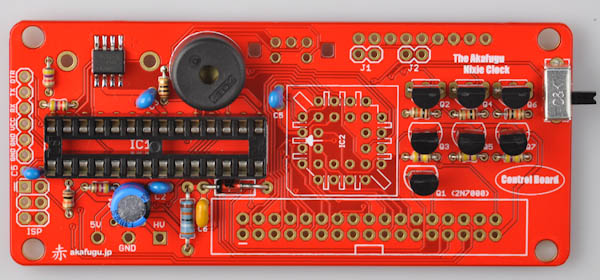
Next is the piezo.
The piezo is not polarized and can go in any way.Bend the legs outward before turning the board over to solder.Clip off the excess parts of the legs after soldering.Step 11 - Serial Header
Now find the single-row 6-pin male header.
Insert the male header so that the short legs go into the the PCB and the long legs stick out on top.The component may fall out when you turn the board over to solder. You may use a small piece of masking tape or similar to hold it in place.Solder only one leg first, then check that the orientation of the component is correct. If not, re-apply heat and adjust as neccesary. Once you are happy with the orientation, solder the remaining legs.Step 12 - 28-pin PLCC Socket
Now solder the 28-pin PLCC socket. There is an indentation on one of the edges, insert it so that it matches the indentation drawn on the PCB silk screen.
The component may fall out when you turn the board over to solder. You may use a small piece of masking tape or similar to hold it in place.Solder only one leg first, then check that the orientation of the component is correct. If not, re-apply heat and adjust as neccesary. Once you are happy with the orientation, solder the remaining legs.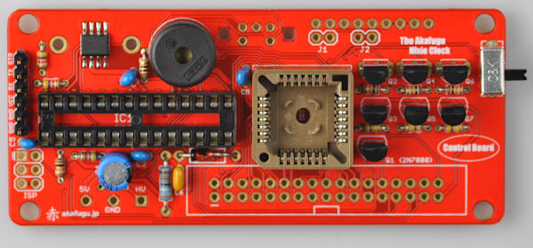
Step 13 - 2x17 Shrouded Male Header
Next, we place the two 2x17-pin shrouded male header.
Insert the male shrouded header so that the open indentation in the middle of the connector matches the square drawing on the PCB silk screen.The component may fall out when you turn the board over to solder. You may use a small piece of masking tape or similar to hold it in place.Solder only one leg first, then check that the orientation of the component is correct. If not, re-apply heat and adjust as neccesary. Once you are happy with the orientation, solder the remaining legs.Step 14 - Inserting the Microcontroller and HV5812
Locate the ATMega328P microcontroller (28 legs) and the HV5812 driver (square).
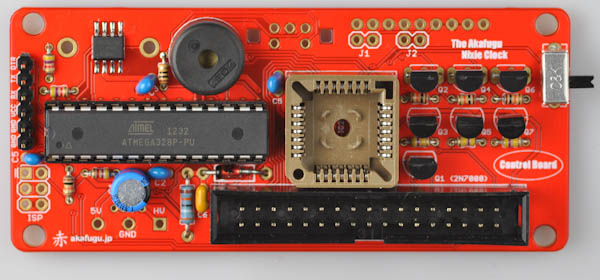
Make sure orientation is correct!
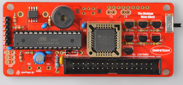
It may be neccesary to bend the legs of the IC slightly inward in order for it to fit. This is best done by pressing it gently against a flat surface.Now, let us insert the HV5812 chip into the socket. Make sure that the orientation is correct: The slanted part along one of the sides of the chip should point downward.
Press it down with even pressure, it should click into place.
Step 15 - Battery Connector Center Pad
Turn the board over.
Note the square pad in the middle of the battery connector silk screen outline on the top right. Melt a bit of solder against this pad. Without solder the battery will not make proper contact.
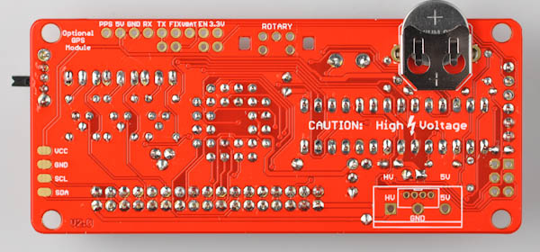
Step 16 - Battery Connector
Now insert the battery connector.
Fit it to match the outline on the PCB silk screen.Turn over and solder.Solder only one leg first, then check that the orientation of the component is correct. If not, re-apply heat and adjust as neccesary. Once you are happy with the orientation, solder the remaining legs.This component will become very hot when soldering, so be careful when touching it.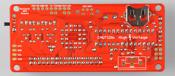
Step 17 - Inserting the Backup Battery
Insert the backup battery, the side marked + pointing up. Push it all the way in.
Step 18 - Screw Terminal
Next up is the screw terminal. Insert it so that the screw holes point inward (up) as seen in the picture.
The component may fall out when you turn the board over to solder. You may use a small piece of masking tape or similar to hold it in place.Solder only one leg first, then check that the orientation of the component is correct. If not, re-apply heat and adjust as neccesary. Once you are happy with the orientation, solder the remaining legs.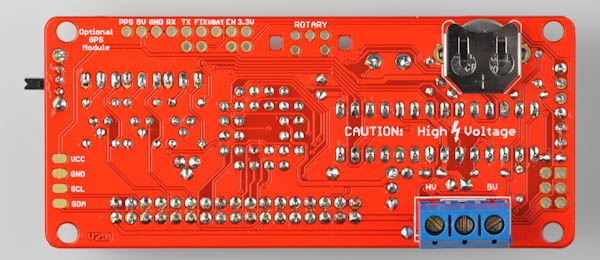
NOTE: In some kits the screw terminal may be green.
Step 20 - Rotary Encoder
Next up is the rotary encoder.
It will only fit one way.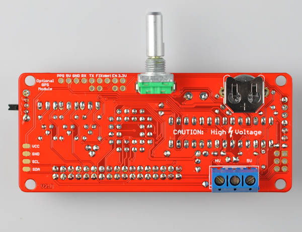
Solder the five round legs. The two clips on the side should not be soldered.
Step 21 - Connecting Cables
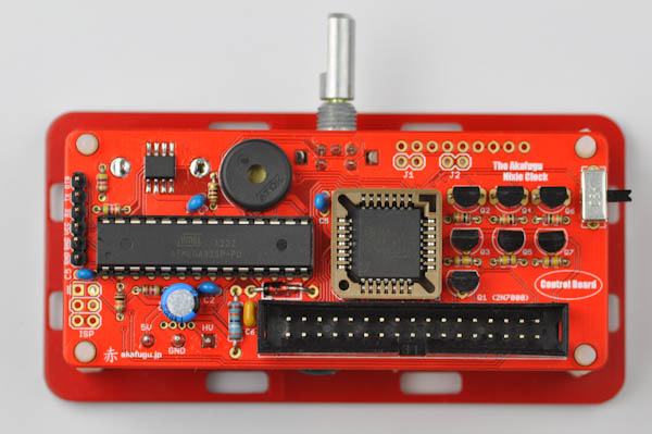
Here is the board with all components connected:
Now it is time to connect the power board to the logic board.
 | WARNING: Make absolutely sure that the cables are connected correctly! If the HV and VCC connectors are mixed up, all the components on the board may end up with 180V applied to them. This will damage all the components beyond repair and render the entire board unusable. |
The three wires you added to the power board are now ready for insertion into the screw terminal on the bottom of the logic board.
Make sure each cable goes to the correct place: GND, VCC and HV on the power board must go to GNC, VCC and HV respectively on the logic board.
Use a small flat or star screwdriver to fasten the wires.
Step 22 - Placing the control board
Insert the logic board on top of the power board, making sure orientation matches. The four holes on the logic board will align with the four spacers you fastened to the power board.
Step 22 - Testing
Now we will test that the microcontroller boots up properly.
Put the board in an open space, and insert the power jack. Make sure you are not touching the board, and then insert the power adapter into the wall plug.
You should hear a small melody playing as the microcontroller boots up.
Step 23 - Remove Power
Remove the power adapter from the wall plug, and then wait at least 30 seconds.
Finally, remove the power jack.
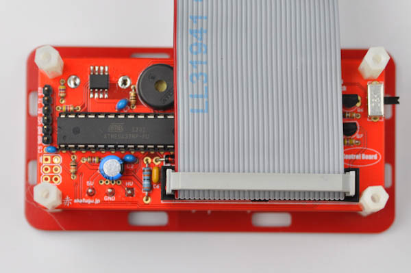
Step 24 - Flat cable
Attach the flat cable as shown in the picture.

Step 25 - Spacers
Locate the remaining four spacers, and screw in each one to fasten the control board to the power board. Again, be go slowly as the nylon spacers are easily damaged.
The logic board preparations are now finished. Continue on to theIN-12 Board Assembly Instructions.